The conversation about Building Information Modeling has matured past the early-2010s debates about whether BIM was worth the cost. Most architecture firms working on commercial projects now operate in BIM environments as their default. The questions that come up are practical ones — where do I get a reliable manufacturer-specific object for an unusual product, how do I know it's accurate, and what's the right way to bring it into a coordinated model?
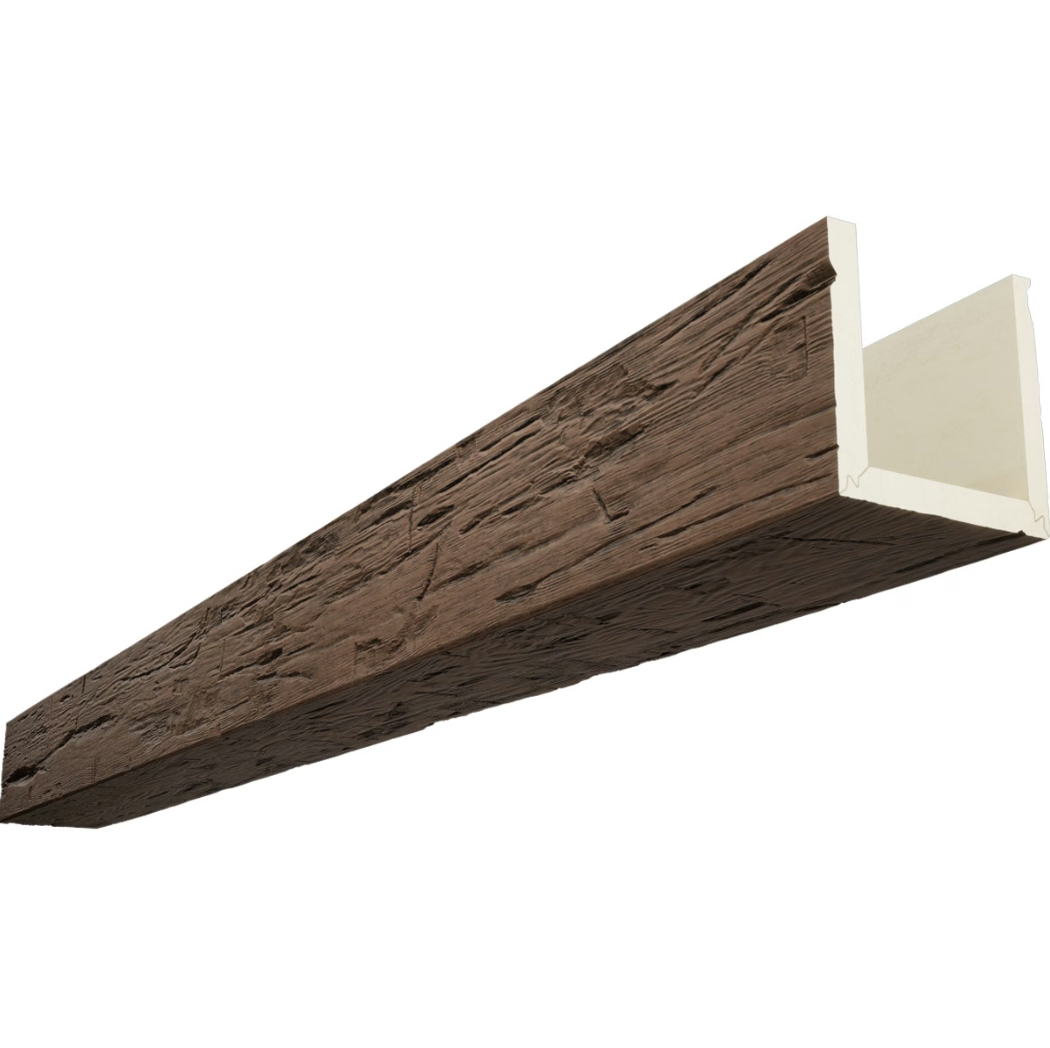
PU faux beams fall into that group of products that BIM managers used to model generically, often with placeholder geometry that didn't reflect what was actually specified. Generic cylinder-on-cylinder blocks floating in space, sized roughly, with finish information handled separately in the specification book. That approach worked for schematic design but fell apart as projects moved into construction documentation, where dimensions, connections, and material performance all needed real data.
Manufacturer-specific BIM objects address that gap, and the quality of those objects has improved meaningfully across the industry.
What Separates Useful BIM Content from Filler
The downloadable BIM landscape is full of objects that look promising in the library browser but create more work than they save once placed in a real project. Understanding what to evaluate before committing a family to your office library saves hours of cleanup on every project that uses it.
What Makes a BIM Object Actually Useful
A downloaded BIM object lives or dies on three characteristics: parametric flexibility, accuracy, and metadata. A Revit family that's just a static block is barely better than a generic placeholder. A family with parametric width, height, length, finish options, and connection details becomes a usable component across multiple projects.
Accuracy matters because the model is only useful if it represents what's actually being built. A faux beam BIM object that uses the wrong dimensional profile — even by a half inch — creates small errors that compound across a model. Over a ceiling with multiple beam runs, those errors accumulate and create coordination problems with adjacent elements like lights, ductwork, and ceiling transitions.
Metadata is the part that's often skipped. A BIM object should carry parameters for manufacturer, product code, finish reference, fire rating if applicable, weight, expected installation method, and any product-specific notes that downstream users need. Without that data, the object is just geometry. With it, the object becomes a meaningful piece of project information that can drive schedules, specifications, and quantity takeoffs.
The best PU faux beam BIM objects pack all three characteristics in. They're parametric across the realistic dimensional range the product line covers, they're modeled to actual installed dimensions including connection detailing, and they carry the metadata needed for downstream coordination.
Where to Find Quality BIM Objects
Three primary sources exist for manufacturer-specific BIM content. The first is the manufacturer's own website. Larger faux beam producers maintain BIM libraries as part of their technical resources, often including Revit families, IFC files, and sometimes ArchiCAD or Vectorworks components. These are the gold standard because the manufacturer maintains them, updates them when product specifications change, and supports them in case of issues.
The second source is BIMobject, BIMsmith, or similar curated libraries. These platforms aggregate manufacturer content under a consistent framework. The advantage is standardization across manufacturers and built-in search functionality. The disadvantage is occasional lag in updates — a manufacturer may revise a product while the BIMobject version remains older.
The third source is general BIM repositories like Autodesk Seek or nationalBIM Library. These tend to be broader but less curated. Quality varies more widely, and the objects don't always come with manufacturer support.
For project-critical work, manufacturer-direct objects are the most reliable starting point. For early-stage design where the specific product isn't yet specified, library aggregators offer broader range at the cost of accuracy.
Common Issues with Downloaded Objects
Working with downloaded BIM objects almost always involves some cleanup. A few issues come up frequently. The first is level of detail mismatch. A manufacturer creates a richly detailed family for product visualization, but its geometry is too dense for the LOD your project requires. Heavy families in large models create performance issues that slow down coordination meetings.
The second is coordinate system alignment. Objects imported from external sources are sometimes modeled with internal coordinate systems that don't align cleanly with project standards. A beam that's two inches off the insertion point in plan view looks fine in isolation but creates clutter at intersections.
The third is parameter naming. Manufacturers use their own internal parameter naming conventions, which may not match your firm's template. Parameters for length might be called "Length_Manufacturer" instead of "Length" in your template, breaking schedules and tags. Linking or renaming parameters takes time but is necessary for the object to participate fully in the model.
A fourth issue, less common but worth noting, is materials and finishes. A faux beam family might ship with materials defined in the manufacturer's marketing render library, which uses high-resolution textures and PBR specifications. Those materials don't always render correctly in the project's main visualization settings, requiring cleanup of the material definitions before everything looks consistent.
From the Library to the Project
The moment a beam family gets placed in an actual project model is when the real test begins. How the family behaves under schedule filtering, coordination with adjacent systems, and downstream procurement workflows ultimately determines whether the download was worth the time spent.

Integrating Beam Objects into Existing Models
The workflow for actually placing beams in a model varies by project type. For new construction, beams usually get placed during interior development, after ceiling heights and structural coordination are settled. The modeler selects the beam family, drops it into ceiling cavities or designated beam pockets, and uses the product's parametric lengths to fill the required runs.
For renovation projects, beams are sometimes placed after demo and existing ceiling conditions are modeled. The modeler needs to confirm beam-to-existing-structure clearances, especially in older buildings where ceiling heights are unforgiving.
In either case, the actual placement benefits from a few specific practices. Coordinate beam runs with lighting layouts before placing, since recessed lighting often fits between beams or requires coordination around them. Tag every placed instance with the correct finish, especially when a project uses multiple beam finishes. Use shared parameters where possible so schedules pull accurate product codes from the model.
The Data Beyond Geometry
A BIM object's metadata layer is what makes it valuable in construction administration. Once a beam family carries manufacturer, product code, weight, and finish information, that data flows into schedules, quantity surveys, and specifications automatically. A modeler doesn't have to type "Beam_Type_A_Oak_8in" into a hundred beam instances individually — the parameter values propagate through the family.
For procurement, this means the BIM model becomes an effective takeoff tool. By filtering schedules by family and parameter values, the project team can extract exactly how many of each beam profile and finish are needed, organized by area. That feeds directly into accurate purchase orders.
For installation, a coordinated model with accurate beam objects lets the contractor pre-plan mounting locations, identify conflicts with mechanical systems before they're discovered in the field, and produce accurate shop drawings. The cost of catching a beam-to-duct conflict in a model is a few minutes of revision. Catching the same conflict on a job site costs thousands of dollars and days of schedule.
BIM Objects and Project Specifications
There's an interesting technical question about how BIM objects interact with project specifications. Some specifications still rely entirely on traditional CSI-format documents, where a beam is described in text and the BIM object is just a visualization. More progressive specifications — often MasterSpec or BSD SpecLink sections — allow specification content to be linked directly to BIM object parameters. The beam object then carries the specification data internally.
For architects working in traditional specification environments, BIM objects serve primarily as geometry and metadata containers. For architects working with BIM-linked specifications, the objects become a much more integrated information source.
Either way, manufacturer-specific objects improve specification quality because they tie descriptive specification language to actual product parameters. The spec can say "8-inch by 8-inch polyurethane faux beam, 16-foot maximum length, Class A fire rating, [manufacturer] [product code] finish [color]" and reference the exact same product that's modeled.
Choosing the Right Level of Detail
A practical question that comes up is what LOD to model beams at. The answer depends on the project phase. In schematic design, a generic placeholder at LOD 200 captures the architectural intent. The walls, ceilings, and structural elements are coordinated, and individual beams don't need real product data yet.
In design development, beams need to reflect the actual specified product, which is where manufacturer BIM objects start to matter. LOD 300 with correct dimensions, finishes, and connection details becomes the appropriate level. At this stage, beam-to-beam, beam-to-wall, and beam-to-ceiling intersections need real geometry.
In construction documentation, LOD 350 or higher is appropriate where beams interact with adjacent systems. Connection details, mounting conditions, and any associated blocking or backing should be modeled. At this stage, the BIM object should be the actual specified product family, not a placeholder.
For facility management handover, the same family often continues into the as-built model, with parameters updated to reflect installed conditions. That model then becomes the basis for ongoing maintenance planning.
Practical Recommendations for BIM Managers
If you're a BIM manager evaluating faux beam objects for inclusion in your office library, a few checks help distinguish quality from frustration. Open the family in isolation and verify all parameters work as expected. Place it in a test project and confirm the geometry renders correctly in your visualization settings. Verify the metadata fields line up with your office template. Test it at several lengths and configurations to confirm parametric flexibility.
Build a small library of the manufacturer objects your specifications reference most often. A short, well-curated library of high-quality objects outperforms a sprawling library of inconsistent content. Once you identify which faux beam products your projects specify most frequently, maintain those objects as standard content and reference them by name in your project setup standards.
The investment in carefully selected BIM objects pays off across years of projects. Once a quality object is in the library, it stays useful for as long as the product itself remains part of the project types your firm handles. Good BIM content is one of those things that quietly compounds in value the longer it's in your toolkit.
Technical References
ASTM standards cited in every specification
Test Data
Lab results from internal testing program
Updated 2026
Reviewed against current product specs