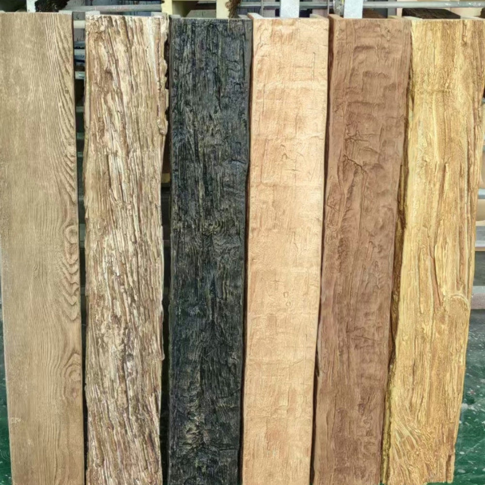
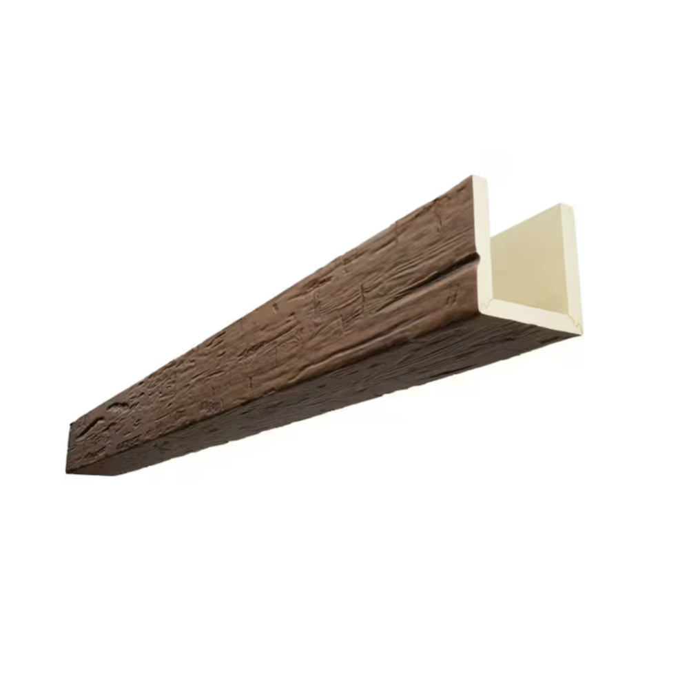
A U-shell beam is half a beam. It has the curved or shaped outer face that the room sees, and an open back that wraps around whatever is behind it. Custom curved U-shell polyurethane faux wood beams are the cleanest way to dress up an existing structural member, hide a piece of mechanical equipment, or build a curved ceiling feature without adding the weight of a full structural beam.
What a U-Shell Does That a Solid Beam Cannot
A solid beam is its own structure. It hangs from the ceiling framing and carries its own weight, plus any specified live load. A U-shell beam is a decorative cover. It wraps around something else — an existing I-beam, a structural glulam, a piece of ductwork, a conduit run — and presents a finished wood face to the room.
This difference matters in several common situations.
Existing structural steel. In commercial retrofits and adaptive reuse projects, the structure often includes steel I-beams or H-beams that the architect wants to hide. Wrapping the steel with a U-shell beam gives the appearance of a solid timber beam while leaving the steel accessible for inspection and fireproofing.
Exposed structural timber. In some designs, the structural beam is meant to be visible, but its finish does not match the surrounding decorative millwork. A U-shell wrap around the structural member provides the desired finish without replacing the structure.
Mechanical concealment. Ductwork, conduit runs, sprinkler mains, and other building services often need to run along the ceiling. A U-shell beam conceals these services while maintaining the architectural language of the space.
Curved ceiling features without structural curves. A U-shell beam can be mounted to a curved track or a series of curved blocking, creating the appearance of a curved structural beam without the cost of a curved structural member. The track does the structural work; the U-shell does the visual work.
For curved U-shell work specifically, the wrap has to follow the curve of whatever it is covering. A steel I-beam that follows a curved ceiling line needs a U-shell that matches. Custom PU molds capture this geometry exactly.
Common U-Shell Applications
The most frequent U-shell beam applications fall into a few well-defined categories.
Wrap-and-finish for existing steel. A 200 by 200 millimeter steel I-beam wrapped in a U-shell becomes a 250 by 250 millimeter faux timber beam. The wrap is sized to fit the steel with a small clearance, typically 10 to 20 millimeters per side, which allows for thermal expansion of the steel and installation tolerance.
Decorative cover for mechanical runs. A rectangular duct 300 millimeters wide by 200 millimeters deep, wrapped in a U-shell, becomes a 400 by 300 millimeter faux timber beam. The wrap is sized to clear the duct plus any insulation or seismic bracing.
Curved false beam. Where the design calls for a curved decorative beam but the structure is straight, a U-shell mounted to a curved track creates the appearance of a curved structural beam. The track is steel or plywood, bent to the desired radius and anchored to the ceiling framing. The U-shell is then screwed to the track, presenting the curved wood face to the room.
Sculptural feature beam. In modern interiors, a U-shell can be mounted to a curved metal armature that follows a non-standard path. The result is a sculptural beam element that traces the ceiling geometry without being a structural member itself.
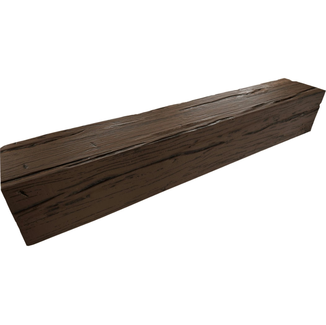
Sizing the U-Shell
The U-shell profile has three critical dimensions: the width across the open face, the depth from open face to the back of the shell, and the thickness of the shell wall.
The width and depth are dictated by what the shell is covering. The factory needs the dimensions of the underlying member plus any clearance requirements. For a steel I-beam wrap, the I-beam's flange width and total depth are the starting point. For a duct wrap, the duct's outer dimensions including insulation are the starting point.
The shell wall thickness is a design choice. A thicker wall (15 to 25 millimeters) reads as a more substantial beam and provides more material for the molded grain. A thinner wall (8 to 12 millimeters) is lighter and easier to handle but may not have enough material to carry deep grain detail.
For curved U-shells, the wall thickness affects how the shell handles the bending. A thick-walled shell holds its shape more rigidly, which is good for consistent curvature. A thin-walled shell is more flexible, which can be helpful for compound curves but may require additional support to hold the desired geometry.
Joining U-Shell Sections
A long U-shell run usually requires multiple sections, joined end-to-end. The joint needs to be structurally sound and visually unobtrusive.
For straight runs, the joint is typically a simple butt joint, with both sections ending at a square cut. The joint is glued and mechanically fastened, with the fasteners hidden along the back edge where they do not show.
For curved runs, the joint is more complex. A curved U-shell section cannot end at a square cut because the cut would not be perpendicular to the beam's centerline. The factory typically cuts the ends with a slight miter that matches the curve's tangent at that point. When two sections are joined, the miters close cleanly and the curve continues without a visible kink.
For multi-section runs, the factory pre-marks the section breaks on a layout drawing so the installer knows exactly where each piece goes. The joints are typically located at points where the curve is at its most natural — often at a 90-degree or 180-degree point on the radius — so any minor joint imperfection is hidden by the geometry.

Finishing the U-Shell
The visible face of a U-shell beam receives the same finish as a solid beam — stain, glaze, and sealer, applied to match the surrounding millwork. The back of the shell, which is not visible after installation, is usually left in a natural or primed finish.
For U-shells that are removable for service access, the finish on the visible face needs to be durable enough to withstand occasional handling. A catalyzed sealer is usually specified for this application. The factory can pre-drill access holes or include removable trim pieces that allow the shell to be lifted off and replaced without damaging the finish.
For U-shells that are permanently installed, the finish can be slightly more delicate, since the shell will not be handled after installation. The factory's standard finish schedule is appropriate.
Installation Sequence
U-shell installation typically proceeds in three steps.
First, the underlying structure is in place. The steel I-beam, the duct, the conduit run, or the curved track is installed and inspected. Any fireproofing, insulation, or seismic bracing is complete.
Second, the U-shell sections are lifted into position. For a curved run, the first section is mounted at one end of the curve and checked for alignment. Subsequent sections are mounted sequentially, with each joint checked before the next section is set.
Third, the U-shell is fastened to the underlying structure. The fasteners are typically self-drilling screws into the steel, or construction screws into the wood track. The fastener heads are hidden along the lip of the shell where they do not show from the room side.
For curved runs, the factory may provide a paper template that marks every fastener location. The installer transfers the template to the underlying structure before mounting the shell, ensuring that every fastener hits its target.
Where U-Shell Work Pays Off
U-shell beams are not a substitute for solid beams. They are a different product for a different purpose. Where the design calls for the appearance of a solid beam but the structure provides the actual support, the U-shell delivers the aesthetic without the structural redundancy.
For curved U-shell work specifically, the combination of factory-molded geometry, factory-applied finish, and clean integration with the underlying structure is what makes custom PU resin the right material. The mold captures the curve. The finish matches the room. The installation is straightforward. The result is a beam element that looks like architecture and installs like a cover.
Technical References
ASTM standards cited in every specification
Test Data
Lab results from internal testing program
Updated 2026
Reviewed against current product specs