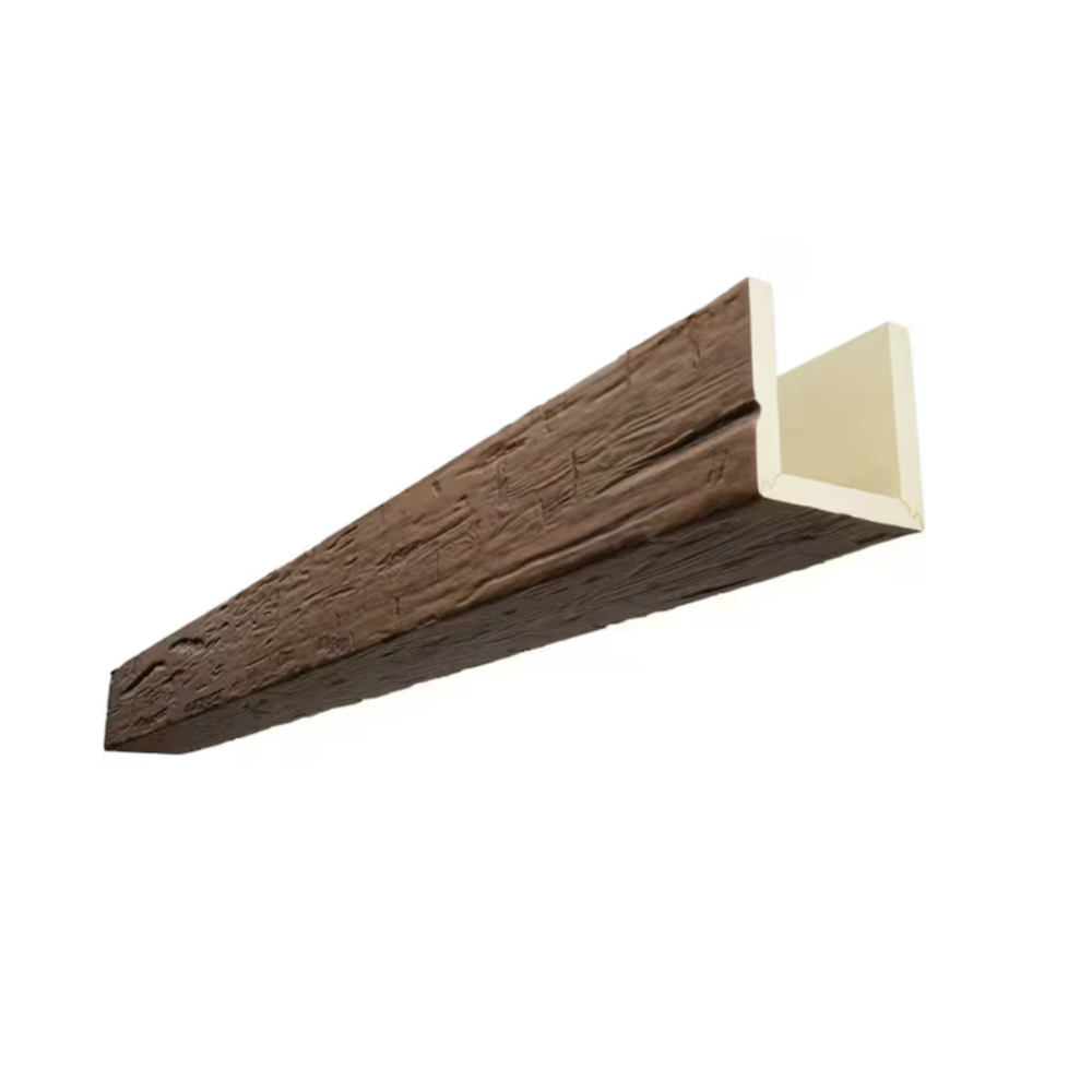
A ceiling layout is not just a plan for where beams will go. It is a design statement that establishes the visual language of the room, defines the relationship between the ceiling and the other surfaces, and creates the framework within which all other decorative elements are understood. The framing beams are the primary structural elements of this layout, and getting their arrangement right is the most important design decision in any beam ceiling project.
Understanding the Hierarchy of Beam Elements
A complete beam ceiling typically involves three levels of elements, each with a distinct visual role.
The primary framing beams are the largest and most prominent elements. They run the full span of the ceiling in one direction and carry the visual weight of the design. In most layouts, the primary beams are spaced at regular intervals that establish the basic rhythm of the ceiling.
The secondary beams run perpendicular to the primary beams and create the cross-hatched pattern that defines the ceiling's visual structure. They are typically smaller than the primary beams, which means they support rather than compete with the main elements.
The tertiary elements fill the remaining spaces and add detail. These may be smaller faux beams, wood panel or shiplap cladding, acoustic panels, or decorative moldings. The tertiary elements complete the ceiling design without adding primary visual weight.
Layout Strategies Based on Room Shape
The shape of the room should drive the beam layout, not the other way around.
For rectangular rooms, the primary beams should run perpendicular to the longest wall. This creates a sense of width and prevents the room from feeling like a tunnel. If the room is significantly longer than it is wide, running the beams perpendicular to the longest wall also makes the ceiling appear shorter and more proportional.
For square rooms, the primary beams can run in either direction, depending on the desired visual effect. Beams running parallel to the entrance emphasize the length of the approach. Beams running perpendicular to the entrance draw the eye across the room toward a focal point.
For L-shaped rooms and other irregular geometries, the layout should be designed around the dominant rectangular zone, with the irregular zones treated as separate elements or connected with secondary beams.
Defining Zones Within Open Plans
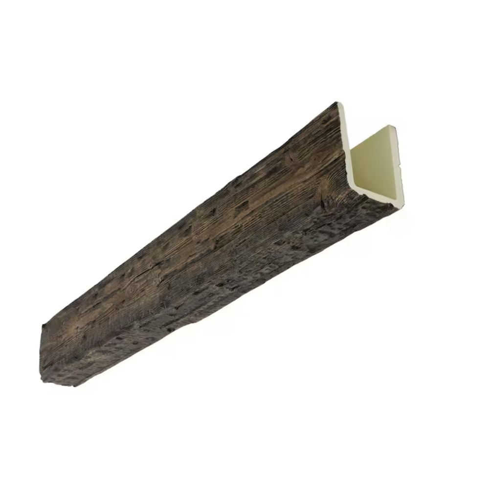
In open-plan spaces, a ceiling layout can define functional zones without using walls or other physical partitions. The beam layout itself becomes the partition.
A living room that flows into a dining area can be divided by changing the direction of the primary beams at the boundary between the two functions. The living room beams run in one direction, and the dining room beams run perpendicular, creating a visual boundary that is clear but not obstructive.
A kitchen that opens to a family room can be divided by a beam that runs across the opening at the transition between the two spaces. The beam serves as a visual marker that says, "you are entering a different zone" without blocking sight lines or dividing the family.
Creating Depth with Layered Layouts
A single level of beams creates a flat, two-dimensional look. A two-level layout with primary and secondary beams creates the illusion of depth, with the secondary beams receding behind the primary beams.
For maximum depth, the secondary beams should be mounted slightly below the primary beams, which is possible when the primary beams are mounted on blocking and the secondary beams are mounted directly to the ceiling. The slight elevation difference creates a shadow line that reads as a step in the architecture.
For a coffered effect, the secondary beams can be joined to the primary beams with decorative corbels or brackets, creating a more substantial visual connection between the two levels. The coffered ceiling has been used in classical architecture for millennia because it creates a sense of grandeur and craftsmanship that a flat ceiling cannot match.
Spacing and Proportion
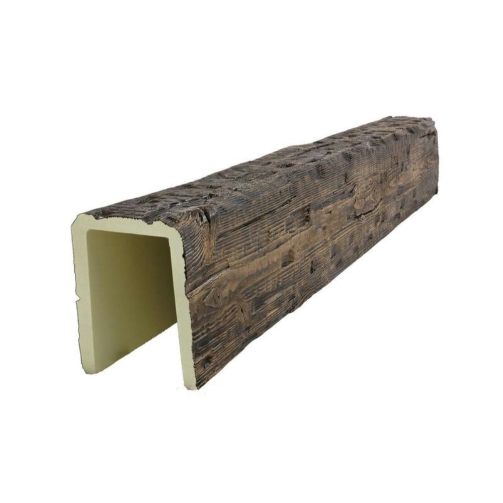
The spacing between beams affects the perceived size of the room and the visual weight of the ceiling. Beams that are spaced widely create a lighter, more open ceiling. Beams that are spaced closely create a heavier, more enclosed feeling.
For standard residential ceilings, a spacing of thirty-six to forty-eight inches between the primary beams is common. This spacing creates a balanced visual rhythm without making the ceiling feel crowded.
For commercial spaces with higher ceilings, the spacing can be wider. A spacing of forty-eight to seventy-two inches is appropriate for ceilings above twelve feet, where the absolute spacing must increase to maintain the same visual proportion.
The ratio of beam width to spacing should be consistent with the overall style of the room. A narrow beam with wide spacing reads as modern and minimal. A wide beam with close spacing reads as traditional and substantial.
Focal Points and Feature Areas
A ceiling layout can be designed around a focal point to create a sense of arrival or emphasis. The focal point may be a fireplace, a large window, a prominent piece of furniture, or simply the center of the room.
At the focal point, the beam layout can be intensified by adding additional elements, reducing the spacing, or introducing a more complex profile. The intensified treatment draws the eye to the focal point and reinforces its importance in the room.
A common focal point treatment is to create a medallion or rosette at the intersection of the primary and secondary beams directly above the focal point. The medallion provides a visual anchor that ties the ceiling to the focal point below.
Coordinating with Structural Elements
The beam layout must be designed around the existing structural elements of the ceiling, including joists, beams, and mechanical systems.
If the existing joists run in a specific direction, the primary beams should run perpendicular to them to create a secondary structural grid. If the primary beams run parallel to the joists, the mounting points will be limited to the blocking installed between joists, which constrains the spacing options.
Mechanical systems including HVAC ductwork, electrical conduit, and fire sprinkler piping should be mapped before the layout is finalized. The beam positions should avoid conflicts with these systems and should allow access for maintenance.
Lighting Integration in Layout Design
The beam layout and the lighting layout should be designed together from the beginning. The position of recessed fixtures, pendant fixtures, and track lighting all affect the beam spacing and positioning.
For recessed lighting, the fixture positions should be planned to fall between the beams, not on top of them. If a fixture must be mounted in a beam location, a shallow-profile fixture or a fixture designed for beam mounting should be specified.
For pendant lighting, the mounting point should be positioned to align with the beam layout. A pendant that hangs between two beams reads as intentional. A pendant that is partially blocked by a beam face reads as awkward.
Documenting the Layout
The beam layout should be documented on a scaled drawing that shows the room dimensions, the beam positions, the spacing between beams, and the relationship to key features like walls, windows, and fixtures.
The documentation should include a section cut or elevation view that shows the relative heights of the primary and secondary beams and the relationship to the ceiling plane.
A material take-off based on the documented layout allows the supplier to provide an accurate quote and allows the installer to verify the order upon delivery.
What Designers Should Know
Designers creating ceiling layouts should think in three dimensions from the beginning. A layout that looks perfect on the plan may not work when the beams are installed because of the way light falls on them, the way they are viewed from different positions in the room, and the way they relate to the furniture and fixtures below.
A full-scale layout mock-up using masking tape or temporary strapping on the actual ceiling is the most reliable way to verify the layout before committing to production. The mock-up allows the designer to stand in the room and experience the proportions before any material is ordered.
Technical References
ASTM standards cited in every specification
Test Data
Lab results from internal testing program
Updated 2026
Reviewed against current product specs