Building owners and renovation managers frequently encounter a frustrating situation: exposed structural beams that either must remain visible due to building codes or cannot be removed without compromising structural integrity. Concrete beams, steel I-joists, and engineered lumber often create awkward ceiling conditions that designers struggle to incorporate into aesthetic schemes. The solution comes in an unexpected form—deep U-channel faux timber sleeves that install directly over existing beams, transforming utilitarian structure into handsome architectural features without demolition or replacement.
Understanding U-Channel Beam Design
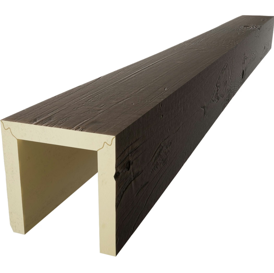
The U-channel profile represents an elegant engineering solution to a common renovation challenge. Rather than manufacturing beams as solid shapes, U-channel sleeves wrap around existing structural members, capturing them within the decorative cover. This approach preserves structural elements while eliminating the complexity of beam removal and replacement.
The manufacturing process creates three-sided covers—two vertical sides and a connecting bottom flange—that join to encircle the existing beam. Installation involves positioning the sleeve around the structural member and securing it at discrete points. The concealed space between sleeve interior and structural beam surface can accommodate wiring, lighting conduit, or sprinkler piping that might otherwise clutter visible ceiling areas.
Deep U-channel profiles accommodate substantial structural beams—widths of 12 inches and depths of 10 inches represent typical maximums for standard products. Larger structural elements may require custom manufacturing or multiple sleeve configurations. When evaluating projects, contractors should measure structural beams carefully, accounting for dimensional tolerances and any surface irregularities that might affect sleeve fit.
Installation Advantages Over Replacement
The most immediate advantage of sleeve installation involves structural preservation. Replacement would require temporary support installation, beam removal, new beam procurement and fitting, and gradual load transfer back to new elements. This process typically spans multiple days, requires engineering oversight, and imposes substantial disruption to occupied spaces. Sleeve installation proceeds without structural intervention, often completing in hours rather than days.
Cost comparison reinforces the practical advantage. A typical beam replacement project might involve $200-400 per linear foot when accounting for engineering, labor, materials, and contingency provisions. Sleeve installation typically costs 20-30% of equivalent replacement, with proportional reductions in project duration and disruption. For projects involving multiple beams across large areas, the cumulative savings become substantial.
Occupied building renovations benefit particularly from sleeve approaches. Hotels undergoing guest room updates, restaurants refreshing their interiors, and office buildings modernizing common areas cannot accept extended closures required by conventional beam replacement. Sleeve installations often proceed during normal operations, with contractors working around ongoing business activities rather than shutting areas for construction duration.
Preparing Structural Beams for Covering
Successful sleeve installation requires careful preparation of existing structural elements. Surface conditions significantly affect both installation efficiency and long-term performance. Engineers should assess structural beams for any conditions requiring attention before covering—corrosion on steel, deterioration of concrete, insect damage in timber, or moisture issues that might continue under the sleeve covering.
Steel beams benefit from surface cleaning before sleeve installation. Loose scale, rust, and accumulated grime should be removed to create clean attachment surfaces. Light rust that has developed naturally over years typically does not require treatment, but any flaking or unstable areas should be addressed. Applying a moisture barrier between steel and sleeve interior prevents future condensation issues in humid environments.
Concrete beams may require more substantial preparation depending on surface condition. Spalling concrete should be repaired, and any exposed reinforcement should receive treatment to prevent continued corrosion. Irregular concrete surfaces might require filling or smoothing to ensure adequate sleeve contact. The goal is creating a clean, stable substrate that supports secure sleeve attachment.
Installation Techniques and Hardware
The actual installation process follows a sequence designed to ensure secure, lasting attachment. Initial positioning establishes sleeve placement, with careful attention to alignment along the beam run. Subsequent steps secure the sleeve progressively, typically beginning at mid-span and working toward ends. This approach maintains alignment while allowing adjustment as attachment progresses.
Attachment hardware varies based on structural substrate and sleeve configuration. Steel beams accept self-drilling fasteners that create their own threads in the metal. Concrete requires expansion anchors or concrete screws that penetrate the substrate sufficiently to resist sleeve weight and any incidental loads. Timber structural elements can use construction screws or specialized timber fasteners designed for the specific connection requirements.
Brackets and support systems provide additional security for spans exceeding practical limits for direct attachment alone. Steel cable hangers, adjustable rod systems, and concealed support brackets transfer sleeve weight to structural elements at intermediate points. These systems remain invisible once installation completes while providing confidence in long-term performance under live loads.
Finishing and Detailing
The transition between U-channel sleeves and surrounding ceiling or wall surfaces requires careful attention. Without proper detailing, these intersections reveal the covering nature of the installation rather than presenting the appearance of authentic exposed beams. Several approaches create seamless-looking transitions appropriate to different design schemes.
Where beams meet walls, end returns create the impression that beams extend into the wall structure rather than terminating at the surface. This detail requires matching beam profile on the wall return, typically extending 4-8 inches before terminating in a clean end. Crown molding or simple trim pieces smooth the intersection between beam end and wall surface.
When multiple beams run parallel, consistent spacing reinforces the appearance of intentional design. Even when structural beams display irregular spacing, covering sleeves can be positioned to create pleasing rhythm across the ceiling plane. This adjustment may require custom sleeve fabrication, but the resulting appearance typically justifies the additional coordination effort.
Lighting integration opportunities multiply with U-channel installations. The sleeve's structural depth accommodates LED strip lighting that creates up-lighting effects along the beam run. Conduit and junction boxes for these fixtures fit within the void space between sleeve interior and structural beam, remaining completely concealed while providing functional illumination.
Customization Options for Design Flexibility
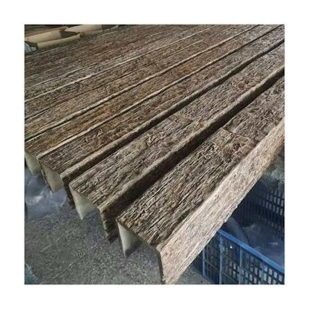
Standard U-channel sleeves offer various wood species appearances, texture depths, and finish options that serve most project requirements. Custom capabilities extend these options to accommodate unique design visions or unusual structural conditions. Understanding available customization helps project managers and designers identify solutions for challenging situations.
Profile customization addresses structural beams that fall outside standard dimension ranges. Extended widths, increased depths, or non-standard proportions can be manufactured to specification. This capability proves valuable for architecturally significant beams that deserve special treatment or for renovation situations where structural elements create unusual challenges.
Finish customization extends beyond standard catalog options. Projects requiring specific color matching, unusual wood species appearance, or distinctive surface treatments can specify custom formulations. Extended lead times typically apply to custom finishes, but the resulting aesthetic integration often justifies the additional scheduling consideration.
Project Applications and Success Factors
Warehouse-to-loft conversions represent ideal U-channel sleeve applications. Existing exposed structural elements that define industrial character can be enhanced rather than concealed, with timber-appearance sleeves transforming utilitarian steel into warm timber aesthetics while preserving structural visibility. The installation proceeds quickly enough to accommodate project timelines that might not support conventional renovation approaches.
Church and institutional spaces frequently display exposed structural elements that renovation projects must address. Large beams supporting high ceilings create acoustic and aesthetic challenges that timber appearance can help resolve. U-channel sleeves provide opportunity for aesthetic improvement while maintaining the honest structural expression these building types typically value.
Commercial tenant improvements often involve landlord-provided structural elements that tenants cannot modify. Rather than designing around awkward beams or accepting ongoing visual compromises, tenants can specify U-channel sleeve installation that transforms existing elements into design assets. The approach requires landlord approval but typically gains acceptance given the minimal disruption and permanent improvement to building aesthetics.
Successful U-channel sleeve projects share common characteristics: careful pre-installation assessment, appropriate preparation of existing structure, quality products from experienced manufacturers, and installation by contractors familiar with the specific systems. When these factors align, the result transforms utilitarian ceiling conditions into handsome architectural features that serve project design goals while respecting structural requirements and budget constraints.
Technical References
ASTM standards cited in every specification
Test Data
Lab results from internal testing program
Updated 2026
Reviewed against current product specs


