Any serious faux beam manufacturer — and any importer or distributor who's made the investment in long-term customer relationships — ships a printed or PDF instruction manual with every order. Not a one-page quick-start. A real manual that walks through pre-install checks, layout planning, mounting, finishing touch-up, and warranty registration. This article walks through the kind of content that belongs in that manual, in roughly the order a contractor or installer should read it.

Section 1 — Receiving inspection
The first thing a contractor does with a faux beam order is verify what was actually delivered matches what was ordered. Skipping this step is the most common cause of mid-install surprises. The manual's receiving section typically covers:
- Box count and labeling verification against the packing slip
- Beam-by-beam visual inspection for shipping damage (compression cracks at the high-density PU beam ends, finish rubs on the bottom face, broken corner detail)
- Cross-section inspection on a single sacrificial beam to verify foam density and skin thickness against published specifications
- Hardware kit verification — brackets, screws, anchors, color-matched touch-up kit, field-repair supplies
- Storage instructions if beams aren't being installed immediately (climate-controlled, flat-stacked, out of direct sunlight)
A good manual photographs each step with a representative beam, the shipping carton, and the hardware kit laid out. The manuals that win installer loyalty are the ones that respect the installer's time — one quick read can confirm what's in the delivery and what isn't.
Section 2 — Acclimation and site preparation
PU faux beams have a brief acclimation period before installation, much shorter than solid timber but real. The acclimation section typically covers:
- 24–48 hours at installation site climate conditions
- Vertical storage with at least three supports across the length to prevent creep deflection
- Avoidance of direct sunlight during storage (UV can shift the finish tone before it's even installed)
- Substrate moisture verification — drywall, plaster, or structure should be fully cured, generally below 12% moisture content for the typical adhesive bond
The manual should include a moisture meter reference reading and a recommended minimum reading for the substrate at install. That number protects the installer from warranty disputes two months later when finish starts to lift.
Site preparation also covers ceiling substrate verification. A common installer mistake is assuming the substrate can carry the load. The manual addresses:
- Wood frame (typical residential) — generally fine for standard residential loads
- Steel frame commercial — verify fastener pull-out strength at the substrate
- Concrete or masonry above drywall — through-bolted connections required, not screws
- Suspended drywall ceiling without blocking — beam-blocking needs to be added before install, ideally during framing
The installer should know the answer to "what is behind this ceiling?" before the first bracket goes up.
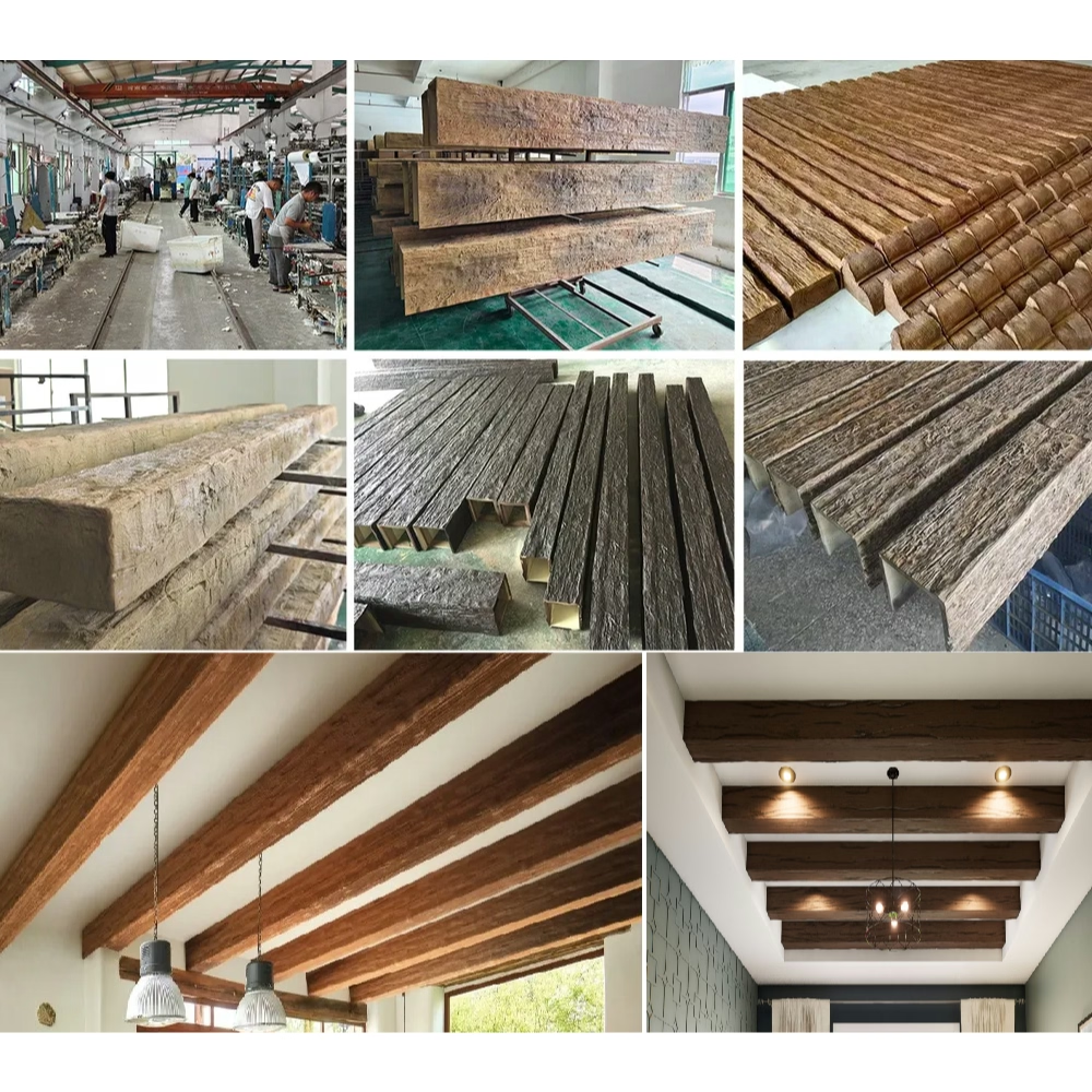
Section 3 — Layout planning and reference lines
Layout planning is where most amateur installations go wrong. The manual walks through:
- Locating the centerline of each beam run with reference chalk lines
- Verifying reference lines against actual architectural drawings and ceiling geometry
- Marking bracket locations along each reference line
- Verifying bracket spacing against the engineering letter supplied for the largest span
A clear diagram showing layout from a top-down view, with bracket location markers and reference dimensions, is worth more than a thousand words. The manuals that work well keep the diagram generic enough to apply to most projects while specific enough that an installer can translate it into actual marks on the ceiling.
For curved runs, the layout section usually adds a curve-specific procedure: snap a chalk line along the intended curve, lay the curved beam in position to verify the curve matches, and identify any field adjustment points. Curves are the highest-risk part of a layout, and the manual is honest about that.
Section 4 — Mounting hardware selection
Mounting hardware depends on three factors: substrate, load, and beam profile. The instruction manual should include a selection table along these lines:
| Substrate | Beam weight per meter | Recommended hardware |
|---|---|---|
| Wood frame, drywall below | < 6 kg/m | Coarse-thread wood screws into blocking, manufacturer-supplied brackets |
| Wood frame, drywall below | > 6 kg/m | Lag screws into blocking or through-bolt to structure |
| Steel stud, drywall below | Any | Toggle bolts or self-tapping metal stud fasteners |
| Concrete or solid masonry | Any | Wedge anchors or sleeve anchors, sized to load |
| Suspended ceiling | Any | Independent blocking to structure above, beam to blocking only |
When in doubt, the manual's standard line is "use the heaviest-duty fastener that physically fits the assembly." Beams don't fail because the fastener was over-specified. They fail because the fastener was under-specified relative to the actual site load.
The hardware kit that ships with the beam usually covers standard residential wood-frame installations. Commercial substrate hardware is typically a separate order, sized against the project's specific structural needs.
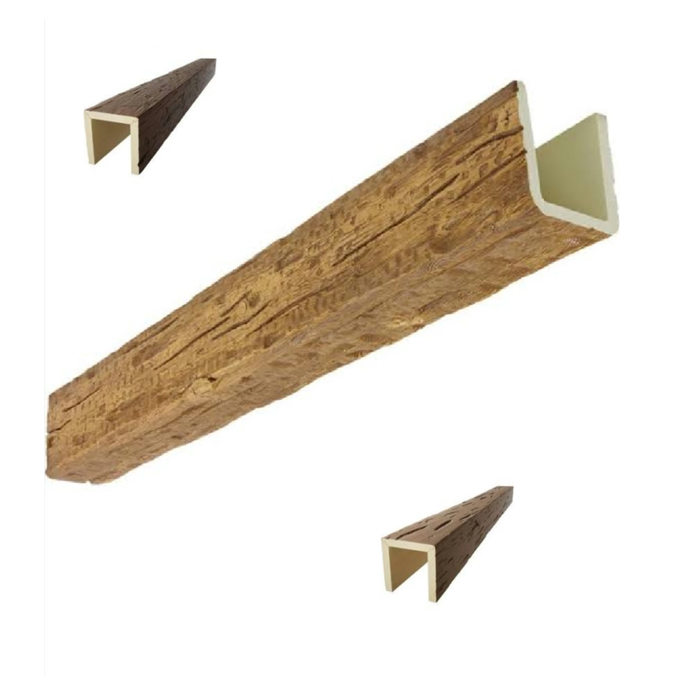
Section 5 — Beam preparation and pre-assembly
Before lifting the beam into place, the manual walks through:
- Wrapping protective foam or cloth around beam ends to prevent finish damage during handling
- Pre-installing internal brackets or steel channels where the beam is rated for hung loads
- Pre-fitting any trim pieces (end caps, decorative corbels) that mount before the main beam goes up
- Verifying cable pathways and penetrations against the beam's shop drawing
Pre-fit takes 5–10 minutes per beam and saves 30–60 minutes of awkward ladder time during the actual lift. The manual emphasizes this in bold type because skipping it is the single most common installer error.
Section 6 — Lifting and fastening
Two-person minimum for any beam over 3 meters. Three-person minimum for any beam over 5 meters or any profile deeper than 10 inches. The manual includes a lifting diagram with sling placement, sling angle from horizontal, and the connection point on the beam where hardware clamps can attach without damaging the finish.
For long beams, the manual walks through:
- Position the beam on temporary support jacks at each end
- Verify the beam is level along its full length
- Drive the first bracket fastener at one end, then check level again
- Work along the beam, driving fasteners in pairs
- Re-verify level at the midpoint before final tightening
The sequence matters. Tightening one end fully before the other end is positioned will pull the beam out of alignment, and re-leveling after that point is a much bigger job.
Section 7 — Joining multiple beams
Most projects involve multiple beams that meet at corners, junctions, or terminations. The manual's joining section typically covers:
- Splice locations for long runs, typically aligned with the underlying framing
- Spline or biscuit joiners where beams butt together
- Color-matched filler compound for any visible joint gaps
- Decorative brackets or straps for exposed splice points where a visible metal joint is acceptable
Custom termination details (corbels, return ends, mitered corners) typically ship pre-cut and pre-finished. The manual instructs the installer to dry-fit each terminator before fastening, and to verify the orientation matches the design drawings before applying adhesive.
Section 8 — Adhesive application
Most faux beam installations use both mechanical fasteners and adhesive. The mechanical fasteners carry the immediate dead load. The adhesive distributes thermal movement and seals the bond against air infiltration. The manual walks through:
- Adhesive selection by substrate (PVA for drywall, polyurethane construction adhesive for wood, epoxy for masonry)
- Bead pattern on the back of the beam, typically a serpentine bead at 50–75 mm spacing
- Open time before bringing surfaces together, typically 5–10 minutes depending on adhesive
- Clamp or temporary support time before fastener removal (where fasteners are used only to hold during adhesive cure)
Adhesive cure times vary by product, and the manual should name the specific adhesive shipped with the order (or recommended for the substrate) along with its working time, cure time, and cleanup solvent.
Section 9 — Finishing touch-up
Even the cleanest installation accumulates minor handling marks during installation. The manual's finishing section typically includes:
- Color-matched filler for small dings, applied with a putty knife and feathered
- Color-matched glaze for surface rubs, applied with a fine brush
- Topcoat pen or spray for finish restoration on cut edges or field-trim areas
- Sanding protocol: never sand the finished face, only field-trim ends before finishing
A small field-repair kit ships with every bulk order. The kit includes a labeled container for each touch-up product, swatches that match the master sample, and application brushes. The manual walks through each kit component with a description of when and how to use it.
Section 10 — Final inspection and warranty registration
Before the installer leaves the site, the manual walks through a final inspection checklist:
- Beam level and plumb against reference lines
- All fasteners at specified torque, with no over-driven screws compressing the beam face
- All joints tight, with no visible gaps larger than 2 mm
- Touch-up applied to any installation marks
- Surrounding ceiling and walls cleaned of adhesive squeeze-out and debris
- Reference photos taken for the project record
Warranty registration completes the install. The manual includes a tear-off card or QR code linking to the manufacturer's warranty portal, with the customer's contact information, project location, and install date. The warranty typically activates within 24–48 hours of registration.
Why the manual matters to importers
Importers and project managers sometimes treat the instruction manual as an afterthought — a short document tucked inside the shipping carton to keep customs happy. The importers who win long-term trust with their customers take a different view. The manual is a continuing technical resource:
- Multilingual editions (typically English plus the importer's local language) demonstrate market commitment
- Updated editions track manufacturing improvements and respond to recurring installer feedback
- A separate technical manual for commercial projects (with structural integration details) supports the higher-stakes segment of the market
- A digital PDF version indexed on the importer's website supports self-service troubleshooting
The instruction manual is the first impression an installer forms of the supplier's professionalism. A well-built manual signals a supplier who's invested in installer success, not just product shipment.
Closing notes
A detailed instruction manual is one of the smallest line items in a beam order and one of the highest-leverage investments in long-term customer satisfaction. Installers who can find what they need quickly, who can match their site conditions to a hardware recommendation on one page, and who can finish a field repair without a phone call to the factory — those installers come back to the same supplier for their next project. The manual is how they remember the way.
Technical References
ASTM standards cited in every specification
Test Data
Lab results from internal testing program
Updated 2026
Reviewed against current product specs


