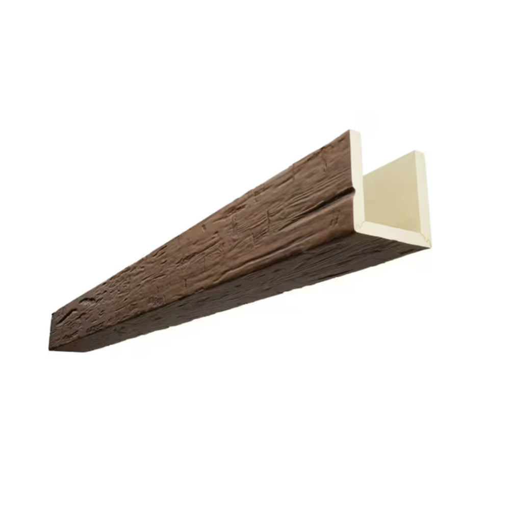
Drafting a ceiling plan with multiple faux beam runs, accurate spacing, and consistent profile representation takes hours when each beam has to be drawn from scratch. For designers handling multiple projects simultaneously, those hours compound quickly. A downloadable CAD block library removes the repetitive portion of the work, letting designers focus on layout decisions rather than line work.
Manufacturers that supply design professionals often bundle their product specifications into CAD-friendly formats. These libraries have become a standard offering in the building products industry, and faux beam suppliers have followed suit with resources specifically tailored to their product lines.
What CAD Blocks Contain
A well-built faux beam block library goes far beyond a simple rectangle. Each block typically represents a beam profile in plan view, elevation view, and section view, drawn to scale from the manufacturer's actual product dimensions. The plan view block shows the beam footprint as seen from above, including width and length. The elevation block shows the profile shape with correct depth and side texture representation. The section block reveals the hollow interior construction.
For polyurethane faux beams, the section block is particularly useful because it shows the wall thickness and the hollow core that defines how the beam is shipped and installed. Designers who understand the section geometry can plan for internal wire routing, mounting bracket placement, and end cap integration without needing to reference separate documentation.
Some libraries include dynamic blocks, a feature available in standard AutoCAD that allows a single block definition to represent multiple sizes. The designer picks a length from a drop-down menu, and the block stretches to match. This eliminates the need for separate block files for every beam length and reduces the library size considerably. For Revit users, equivalent functionality comes through parametric families that adjust dimensions automatically.
Format Compatibility
Most CAD block libraries are distributed in DWG format, which AutoCAD and a wide range of compatible programs read natively. For Revit users, the same library is usually offered in RFA format as a family file. Some manufacturers also provide DXF versions for users of lighter-weight CAD programs, as well as PDF reference sheets for designers who need dimensional information without opening a CAD file.
SketchUp users often look for SKP versions of beam profiles, and a few manufacturers include these in their downloadable resources. The file format ecosystem is fragmented, and serious CAD libraries often include multiple formats to accommodate the range of platforms that design firms use.
For designers working in Vectorworks, ArchiCAD, or other niche platforms, the DWG or DXF files can usually be imported directly. The import process preserves line work, dimensions, and layer assignments, though some platform-specific features may require minor cleanup after import.
Layer Standards and Drawing Conventions
A useful CAD block library organizes blocks according to standard layer conventions. Layers such as BEAM-FLOOR-PLAN, BEAM-ELEVATION, and BEAM-SECTION let designers control visibility and line weight independently. A typical ceiling plan shows only the BEAM-FLOOR-PLAN layer, while a detail sheet can display the elevation and section blocks at larger scale.
Line weight conventions matter when the drawing will be plotted at architectural scales. A beam outline drawn at the default line weight appears too thin on a plotted 1/4 inch equals 1 foot plan. CAD libraries built for architectural use typically pre-assign line weights that match common plot configurations, so designers do not need to adjust them manually.
Annotation blocks are sometimes included alongside the beam geometry. These blocks represent text labels, dimension markers, and callout symbols that designers attach to beam runs. Including the annotation as part of the library speeds up the labeling process and ensures consistent terminology throughout the drawing set.
Saving Time on Repetitive Layouts
The time savings from a CAD block library become significant on projects with multiple ceiling zones. A typical residential project might have beams in the great room, the kitchen, the master bedroom, and a covered outdoor area, each with different orientations and spacing patterns. Drawing each beam manually consumes time, but inserting a block from the library takes seconds.
On large commercial projects, the savings multiply further. A hotel lobby might have dozens of beams arranged in a geometric grid pattern. Drawing each one individually could take half a day. Using blocks, the same layout is completed in an hour, leaving more time for the design decisions that actually require human judgment.
The library also helps ensure consistency across the drawing set. When beams in different views all come from the same source block, the dimensions and proportions match exactly. This consistency reduces the time spent cross-referencing views during quality control and minimizes the risk of dimension errors that can lead to installation problems on site.
Maintaining the Library Over Time
A CAD block library should not be treated as a static resource. Manufacturers update their product lines, retire older profiles, and introduce new sizes and textures. Designers who download the library once and never update it may find themselves working from outdated specifications years later.
Most manufacturers host their block libraries on a dedicated downloads page that is updated whenever the product line changes. Designers can check this page periodically, especially when starting a new project that involves a profile they have not used recently. Some manufacturers send email notifications when significant updates occur, which is the easiest way for busy designers to keep their resources current.
For design firms that maintain a centralized CAD library, designating one person to download and organize manufacturer updates keeps the firm's resources in good order. The designated librarian can place new blocks in the firm's standard folder structure and remove obsolete blocks, ensuring that the entire team works from a consistent set of resources.
Using Blocks in Client Presentations
Beyond the drafting process, CAD blocks serve a valuable role in client presentations. A layout drawn with accurate beam blocks looks professional and conveys the design intent clearly. Clients can see how the beams relate to walls, furniture, and other features in the plan, which helps them understand the spatial effect of the ceiling design.
Some designers take this further by rendering the CAD layout into 3D visualizations that incorporate the beam blocks as the basis for the ceiling model. The accuracy of the original block representation carries through to the 3D render, which means the client sees a visualization that matches what will actually be installed. This level of accuracy builds confidence and reduces the number of revisions requested during the design phase.
For designers who work with clients remotely, sharing the CAD file with embedded beam blocks lets the client open the plan on their own computer and explore the layout at their own pace. This collaborative approach shortens the feedback loop and produces better design outcomes than a series of emailed PDF snapshots.
Library Limitations to Keep in Mind
While CAD blocks are valuable drafting tools, they represent idealized geometry rather than the exact finished product. The actual installed beam may differ slightly from the block due to manufacturing tolerances, field conditions, and installation variations. Designers should always verify critical dimensions against the manufacturer's current specification sheet before issuing drawings for construction.
Custom profiles that fall outside the standard library are sometimes required for unique architectural features. In these cases, the library provides a useful starting point but does not replace the need for custom block creation. Designers can modify an existing block to represent the custom profile, using the standard block as a dimensional reference.
Despite these limitations, a well-maintained CAD block library remains one of the most practical productivity tools available to design professionals working with faux beams. The time saved on drafting, the consistency gained across drawing sets, and the clarity provided in client presentations all contribute to smoother projects and more satisfied clients.

Technical References
ASTM standards cited in every specification
Test Data
Lab results from internal testing program
Updated 2026
Reviewed against current product specs