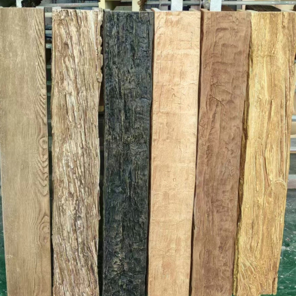
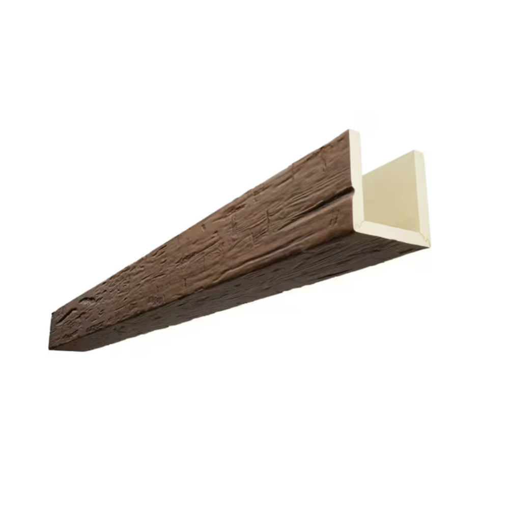
A grid style ceiling layout is one of the more reliable architectural moves for organizing a large interior space. The grid provides visual rhythm, defines zones within the room, and gives the ceiling an architectural presence that flat drywall or plaster can't replicate. Polyurethane faux wood beams have made the grid layout accessible to projects that historically would have either skipped the coffered effect or committed to a solid timber budget.
The reason PU faux beams work so well for grid layouts is that the production process favors repetition. The factory pours each beam from the same mold, finishes each beam with the same stain system, and ships each beam to the same specification. The result is a series of beams that match precisely across the entire ceiling, which is the consistency that makes a grid layout work.

The visual logic of a grid layout
A grid ceiling layout is essentially a series of beams running in two directions, crossing at regular intervals to form a pattern of rectangular panels. The visual logic is simple but effective:
- Repetition creates rhythm. The eye reads the regular spacing as a deliberate pattern rather than as random architectural elements.
- The pattern organizes the room. The grid panels can correspond to furniture groupings, lighting zones, or circulation paths.
- The intersections become focal points. Each crossing of two beams is a natural place for a feature element — a recessed light, a small pendant, a ceiling medallion.
- The panels become canvases. The space between the beams can be finished in a contrasting material or color, which adds another layer to the composition.
The grid works across architectural styles because the geometric logic is universal. The finish and the proportions change with the style, but the underlying grid pattern remains the same.
Proportions for grid layouts
Grid layouts follow specific proportional guidelines that determine whether the pattern reads as elegant or as overworked:
- Beam depth of one-tenth to one-twelfth of the ceiling height. A 3 m ceiling gets a 250 mm to 300 mm deep beam.
- Beam width of 1.5 to 2 times the depth. A 300 mm deep beam is typically 450 mm to 600 mm wide.
- Panel aspect ratio close to square or slightly rectangular. A 2 m by 2 m panel or a 2 m by 2.5 m panel reads as comfortable; a 2 m by 4 m panel reads as corridor-like.
- Beam profile that matches the architectural style. Chamfered edges for contemporary, stepped faces for traditional, smooth returns for transitional.
These proportions produce a grid that reads as architectural rather than as decorative. Beams that are too small disappear into the ceiling; beams that are too large overwhelm the room. The proportions above land in the middle.
Why the grid pattern works for large rooms
Grid layouts are particularly effective in large rooms because the human eye needs organizational cues to read a large space. A 6 m by 8 m great room with a flat ceiling reads as a single large space; the same room with a grid of beams reads as a series of defined zones.
The grid also helps with proportion. Large rooms often feel too tall or too wide relative to the furnishings. The grid breaks the volume into smaller perceived units, which makes the room feel more intimate without changing its actual dimensions.
For rooms with multiple functions — a great room that includes a seating area, a dining area, and a kitchen — the grid can define each function without requiring walls or other physical separations. The eye reads the grid panels as zones, and the furniture arranges itself within the implied zones.
The PU advantage in grid production
Solid timber beams in a grid layout require substantial material and labor. A 6 m by 8 m great room with a grid at 2 m intervals has roughly 50 m of beam length. The total material at solid timber proportions runs several hundred kilograms, requiring coordinated lifts and structural framing reinforcement.
PU faux beams at the same dimensions weigh a fraction of the equivalent solid timber. A typical grid layout in PU can be installed by two people with a scissor lift over the course of a few days. The structural framing doesn't need to be reinforced, the install doesn't require a crane, and the labor runs in a fraction of the time.
The visual result is essentially identical. The grid reads as a coherent architectural composition because all the beams match in profile, finish, and proportion. The factory production process favors this consistency in ways that solid timber production doesn't.
Coordinating with lighting
Grid layouts provide natural opportunities for integrated lighting, and the lighting plan should be coordinated with the grid pattern from the start:
- Recessed downlights can be centered in each grid panel, providing ambient lighting distributed across the ceiling.
- Linear LED strips can run along the inner edges of the beams, providing accent lighting that highlights the grid pattern.
- Pendant fixtures can hang from the beam intersections, providing feature lighting at each crossing.
- Cove lighting can run along the perimeter of the grid, providing indirect lighting that washes the walls.
The factory can integrate the cutouts and channels needed for each lighting approach. Recessed downlight openings, linear LED channels, junction boxes for pendant suspension, and conduit channels for low-voltage cabling can all be specified at order time.
Acoustic considerations
Grid ceilings have specific acoustic properties. The pattern of beams and panels produces a slight diffusion of sound waves, which can help with speech intelligibility in large rooms. The hard beam surfaces also reflect sound, which can contribute to a live acoustic environment if not managed.
For rooms that need acoustic treatment, the beams can be specified with perforated acoustic backing that adds absorption at the speech-frequency range. The perforation pattern is micro-scale and doesn't affect the wood-grain appearance at typical viewing distances.
Acoustic panels can also be installed in some of the grid panels, leaving other panels as finished surfaces. This creates a pattern that combines acoustic function with visual rhythm. The factory can produce acoustic panels to match the beam finish, maintaining the aesthetic coherence of the grid.
Where grids work and where they don't
Grid layouts are the right specification for rooms that benefit from architectural organization:
- Large great rooms with multiple functions or large expanses of ceiling.
- Formal dining rooms with high ceilings that need architectural presence.
- Libraries and studies with substantial ceiling volume.
- Hotel lobbies with large floor plates that need visual organization.
- Restaurant dining rooms with high ceilings and substantial volume.
- Commercial reception halls with large open areas.
Grid layouts aren't the right specification for rooms that don't support the pattern:
- Small rooms with low ceilings. A grid in a 3 m by 3 m room with 2.7 m ceilings reads as overwrought.
- Rooms with low ceilings. Below 2.7 m, the grid eats volume the room can't spare.
- Rooms with extensive skylights. A grid competes with skylights for visual attention.
- Rooms that want to feel intimate. A grid reads as formal and architectural. Smaller rooms that want to feel cozy should use simpler ceiling treatments.
For rooms that don't support a grid layout, alternative ceiling treatments include a single statement beam, a perimeter cove, a tray ceiling, or a simple flat ceiling with statement lighting.
Coordinating with adjacent spaces
Grid layouts in one room often need to coordinate with the ceiling treatments in adjacent rooms. The transitions are the design-critical details:
- Grid terminating at a doorway. The beams terminate at the door header with a return leg or a decorative end cap. The transition is a small detail that should be specified before the beams are ordered.
- Grid transitioning to a flat ceiling. The beams terminate at a defined line on the ceiling, often with a perpendicular beam that acts as a transition element.
- Grid continuing into an adjacent room. The pattern extends across the rooms, which works in open floor plans where the visual continuity is desired.
- Grid in one room and a different pattern in the adjacent room. The two patterns meet at a defined transition, often a beam that acts as a visual separator.
The transitions should be detailed before the beams are ordered, because field adjustments are time-consuming and less accurate than factory-prepared terminations.
Working with the ceiling plane
Grid layouts work with flat ceilings, vaulted ceilings, and coffered ceilings. The relationship between the beams and the ceiling plane determines how the grid reads:
- Flat ceiling with beams applied to the surface. The simplest configuration. The beams are decorative elements on a flat plane.
- Dropped grid with the panels lowered. The beams and panels form a true coffered ceiling, with the panels recessed below the surrounding ceiling plane.
- Raised grid with the panels elevated. The beams form a frame around raised panels, which creates a different visual effect.
- Vaulted ceiling with the beams following the vault. The grid pattern follows the curvature of a vaulted ceiling, which adds complexity to both the design and the installation.
The right configuration depends on the ceiling structure and the design intent. The factory can produce beams for any of these configurations, but the specification has to be clear about which one is intended.
Installation in an existing room
Grid layouts in existing rooms require more preparation than new-construction installs. The ceiling needs to be assessed for structural capacity, and the grid pattern has to be designed around any existing services.
A typical install sequence:
- Survey the existing ceiling and identify the framing, the services, and any anomalies.
- Design the grid pattern, working around existing services and aligning with the room's geometry.
- Install blocking along each beam line. This is the most time-consuming step.
- Hang the beams in sequence, starting from one corner of the room.
- Connect factory-cut service openings to existing services.
- Finish touch-ups and final inspection.
The blocking work is the most variable part of the install. In rooms with substantial existing services, the blocking has to route around the services and may require custom shimming. In rooms with cleaner ceilings, the blocking is more straightforward.
Long-term performance
PU faux wood beams in a grid layout should provide twenty years or more of service before any refinishing is needed. The factory finishes are UV-stable for interior use, and the foam core is dimensionally stable across humidity changes. The grid pattern doesn't develop any wear issues specific to the layout; the beams age the same way they would in any other configuration.
Touch-up kits are available from the factory for any damage that occurs. The repair process is the same as for any PU faux beam — sand the affected area, apply the matching touch-up stain, and seal with the same top coat used at install. A grid layout makes touch-ups slightly more visible because the pattern draws attention to any inconsistency, but the touch-up system is designed to address this.

Working with the lighting designer
Grid ceilings provide substantial lighting infrastructure, and the lighting designer should be involved during the grid specification phase. The lighting plan determines the cutouts, junction boxes, and conduit channels that need to be factory-integrated into the beams.
The coordination between the grid layout and the lighting plan is one of the more important parts of the design process. A grid that supports the lighting design produces a better result than a grid that fights it.
A note on the right number of beams
Designers sometimes over-specify grid layouts, adding more beams than the room needs. The right number of beams is the minimum that creates the architectural rhythm without overworking the ceiling. For a typical 6 m by 8 m great room with a 3 m ceiling, a grid at 2 m intervals in both directions produces roughly 50 m of beam length, which is appropriate. Adding more beams at 1.5 m intervals would produce roughly 75 m of beam length, which can read as overworked.
The eye needs some negative space between the beams for the pattern to register. A grid that fills the entire ceiling with beams reads as busy rather than as architectural. Designers should be willing to recommend against adding more beams when the room already has the rhythm it needs.
Technical References
ASTM standards cited in every specification
Test Data
Lab results from internal testing program
Updated 2026
Reviewed against current product specs