Every long beam run ends with the same problem. The room is 28 feet across. The longest available beam is 16 feet. Something has to join two beams together at the 14-foot mark.
The wrong splice looks like a mistake. The right splice either disappears entirely or becomes part of the design — a deliberate visual element that reads as craftsmanship rather than compromise. The difference comes down to choosing the right connector and splice hardware for the situation, and executing the joint cleanly.
Types of beam joints in faux beam installations
Several joint configurations are used in PU faux beam work. Each has a specific application and a specific aesthetic.
Butt joint. The simplest joint — two beam ends cut square, butted against each other. The joint is held by a hidden splice plate or backing block. A butt joint is the weakest aesthetically because the seam is often visible. It works only when the joint will be hidden by a decorative element (a corbel, a hanging fixture, or a feature that intentionally falls at the joint location) or when the beam is short enough that no splice is needed.
Mitered splice. Both beam ends are cut at 45 degrees, creating a longer diagonal gluing surface. The miter hides the seam better than a butt joint because the joint line is interrupted by the diagonal cut. Mitered splices are standard for runs that need to look continuous across the splice.
Scarf joint. A more complex joint where each beam end is cut with a long taper, creating an extended glued surface. The scarf joint is the strongest aesthetic splice — when done well, the joint is invisible. It is also the most demanding to execute, requiring precise cuts and careful alignment.
Decorative strap joint. The splice is intentionally exposed as a decorative metal strap across the joint. This is a design choice rather than a way to hide the joint. The strap is typically a forged or cast metal piece in a black, bronze, or antique finish. Decorative straps work well in Tuscan, Old World, and craftsman-style interiors.
Hinged corner. Where two beams meet at a corner, the joint can be a mitered corner or a housed joint. The mitered corner is cleaner; the housed joint is more structurally sound. For zero-load decorative beams, either works.

Hidden splice hardware
For joints that should not be visible, several hardware options exist.
Steel splice plates. A flat steel plate, typically 6 inches wide by 18 to 24 inches long, is screwed into the back of one beam and then slides into the next beam as the two are joined. The plate is hidden inside the hollow beam when installed. This is the workhorse of hidden splices in faux beam work.
Wood backing blocks. For solid-core faux beams, two wood blocks are glued and screwed into the ends of each beam, creating an overlapping connection. The blocks extend 6 to 12 inches into each beam, giving a glued surface of 12 to 24 inches. This is stronger than a steel plate but only works with solid-core beams.
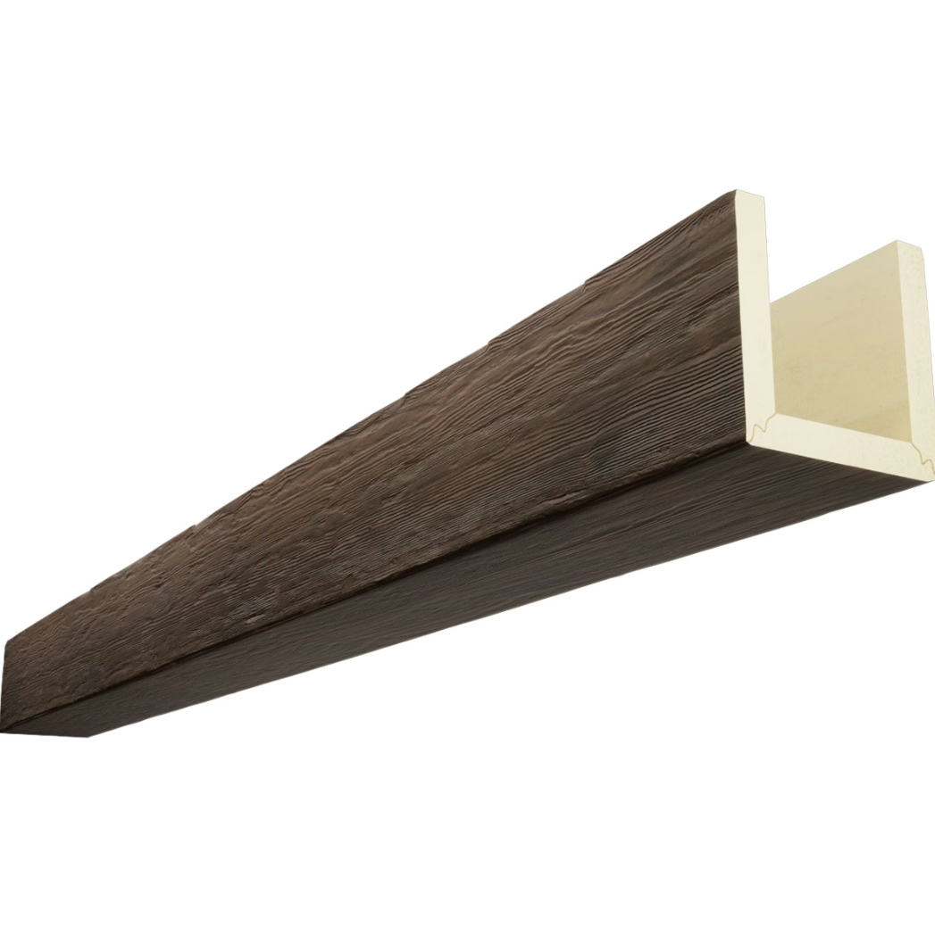
Internal C-channel. A continuous steel channel runs inside the hollow beam along its length. When two beams are joined, the channel bridges the joint and provides alignment and load transfer. This is the best choice for long runs where the splice needs to handle the weight of the continuous beam.
Splined joint. A thin plywood or hardboard spline is glued into matching grooves cut into both beam ends. The spline provides alignment and adds glue surface. Combined with a hidden plate, this is a robust joint.
The choice of hardware depends on the beam profile, the load requirement, and whether the joint is meant to be invisible or decorative.
Decorative strap plates and corner brackets
When the splice is meant to be visible, the hardware becomes part of the design language.
Flat strap plates. A flat metal strap runs across the joint, perpendicular to the beam length. Straps are typically 2 to 4 inches wide and 18 to 30 inches long, depending on the beam size. They are pre-drilled with decorative nail or bolt heads. Common finishes: flat black, oil-rubbed bronze, antique copper, pewter, hammered iron.
Hinged corner brackets. Where two beams meet at a corner, a decorative L-shaped bracket wraps the outside corner. These are common in Tuscan and Mediterranean designs where the corner detail is part of the aesthetic.
U-straps. A U-shaped strap wraps around three sides of the beam at a splice point. The U-strap is more visually substantial than a flat strap and works well in heavy timber applications where the splice detail should look rugged.
Bolt heads. Decorative bolts with hexagonal or hammered heads can be added to flat strap plates to enhance the appearance. The bolts are typically not structural — they are pre-threaded into the strap for visual effect.
The decorative hardware is usually purchased separately from the beams, but quality manufacturers offer matching hardware lines that coordinate with the beam finish. The color and texture of the strap metal should complement the beam stain — a warm bronze strap with a dark walnut beam, a black iron strap with a weathered oak beam, and so on.
Splice placement strategy
The position of the splice in a beam run matters more than the hardware itself. A poorly placed splice will always look wrong regardless of the hardware quality.
Place splices where they are supported. A splice that falls between two joists will eventually sag as the beam moves. A splice that falls directly over a joist or blocking point has continuous support.
Avoid splices at the midpoint of the span. The midpoint is where the beam is most visible and where any sag will be most apparent. Place splices at the 1/4 or 3/4 point of the span instead.
Align splices with room features. Place splices directly above a structural column, a wall corner, or a feature like a hanging light. The eye expects a visual event at that location and accepts the splice.
Stagger splices in adjacent parallel beams. If two parallel beams both need to span a long distance, do not place the splices at the same location in each beam. Stagger them by 4 to 8 feet so the splices do not line up visually.
Hide splices behind corbels or ceiling features. A corbel at the joint location, a soffit transition, or a dropped ceiling feature all provide cover for a splice.

Load transfer at splice points
The mechanical engineering of a splice depends on whether the beam is zero-load, light-load, or structural.
Zero-load. The splice only needs to hold the two beam sections together and transfer the minor weight of the beam itself. A simple steel plate or backing block is sufficient. The splice does not need to develop the full strength of the beam.
Light-load. The splice must transfer any small loads applied to the beam (lighting, signage) across the joint without movement. A steel C-channel or a bolted splice plate is the standard detail.
Structural. The splice must develop the full moment and shear capacity of the beam at the joint. This is a different engineering problem entirely. For structural applications, faux beams are not appropriate — solid timber or steel is required.
For zero-load and light-load applications, the splice detail should still be documented. The installer should know the rated capacity of the splice and confirm that the splice location and hardware meet that rating.
Material compatibility
Splice hardware must be compatible with both the beam material and the installation environment.
Stainless steel for humid and coastal environments. Standard zinc-plated or powder-coated steel will corrode in humid conditions. The corrosion can stain the beam and eventually compromise the connection. Specify 316 stainless steel for any humid or coastal application.
Aluminum for lightweight installations. Aluminum splice plates are lighter than steel and corrosion-resistant. They are also softer and not as strong. For residential zero-load applications, aluminum is fine. For commercial or light-load applications, steel is preferred.
Bronze or brass for decorative applications. Where the strap is meant to be visible and the design calls for a warm metal finish, solid bronze or brass hardware is appropriate. These materials are expensive but they age well in interior applications.
Coated steel for standard interior applications. Standard zinc-plated or powder-coated steel is the default for most residential installations. The coating protects against the moderate humidity of interior spaces.
Common installation mistakes
Several splice mistakes appear repeatedly in residential and commercial installations.
No splice plate at all. The two beam ends are butted against each other and held by adhesive alone. Over time, the adhesive fails and the joint separates. This is the most common splice failure.
Splice plate too short. A 4-inch splice plate in a 10-by-12 beam is undersized. The plate should extend at least 12 inches into each beam for adequate load transfer.
Mitered splice without internal support. The mitered cut looks clean but the joint has no internal hardware. A mitered splice should always have a hidden plate or backing block — the miter is for aesthetics, the hardware is for structure.
Visible gap at the joint. The two beams are not brought tightly together, leaving a visible gap. The gap may be small at installation but expands as the building moves. Tight joints at installation prevent this.
Screws visible on the beam face. Screws that secure the splice hardware have been driven through the front face of the beam instead of the back or sides. They are now visible and need to be filled and touched up — if they were even noticed during installation.
Splice positioned where the beam direction changes. The splice falls at a corner or transition point where one beam butts against a perpendicular beam. The perpendicular beam is the structural support; the splice is decorative. The result looks confused.
Choosing the right approach for the project
The splice strategy should be decided during the design phase, not during installation. A project that needs two splices per beam run has different layout and budget implications than a project that can use continuous beams.
Continuous beams. When the longest single-piece beam available covers the span without splicing, the project is straightforward. No splice hardware, no splice placement planning, no risk of joint failure.
Single splice. When one splice is needed, the placement and hardware can be optimized. Choose the splice location strategically, use the appropriate hardware, and finish the joint cleanly.
Multiple splices. Long commercial runs or projects with very long spans may require multiple splices per beam. The splices should be staggered and the hardware upgraded to handle the cumulative load.
The goal is a finished beam run that looks like a single continuous timber, or that celebrates its joints as deliberate design elements. The wrong hardware in the wrong place always shows. The right hardware in the right place becomes invisible.
Technical References
ASTM standards cited in every specification
Test Data
Lab results from internal testing program
Updated 2026
Reviewed against current product specs

