The beam fell off the ceiling six months after installation. The homeowner had just finished a dinner party. No one was hurt — the beam landed on the dining table rather than a guest — but the damage was significant and the embarrassment was worse.
The cause was inadequate mounting hardware. The installer had used light-duty residential brackets on a 12-foot 10-by-10 faux beam, screwed into drywall rather than into blocking or joists. The beam weighed about 90 pounds; the brackets could hold 30 pounds; the drywall anchors could hold 20 pounds. The math was never going to work.
Heavy-duty hardware for secure beam mounting is specified to the actual loads and the actual ceiling conditions. The right hardware is the difference between a permanent installation and a future failure.
Components of a secure mounting system
A complete mounting system includes several components that work together.
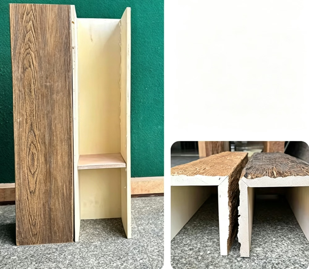
The beam itself. The hollow polyurethane beam has a thin wall section that the hardware engages. The hardware must be designed for the specific beam wall thickness and foam density.
The mounting bracket. The metal or wooden bracket that transfers the beam weight to the building structure. Brackets come in several configurations.
The fastener. The screw, bolt, or nail that connects the bracket to the building structure. The fastener must be appropriate for the structural material.
The blocking or structural support. The wood or metal element inside the ceiling that provides the anchor for the fastener. Blocking must be properly sized and securely fastened to the building structure.
The adhesive. The construction adhesive that bonds the beam to the ceiling. Adhesive is a supplement to mechanical fastening, not a replacement.
Each component must be correctly specified and correctly installed. A weakness in any one component compromises the whole system.
Types of mounting brackets
Several bracket configurations address different installation requirements.
L-bracket. A simple angle bracket that mounts to the side of a joist or blocking. The beam rests on the horizontal leg of the L; the vertical leg is fastened to the support. L-brackets are appropriate for residential zero-load installations.
Cleat bracket. A wooden cleat (typically 2x4 lumber) mounted to the ceiling. The beam slides over the cleat and is screwed into it from the side. Cleat brackets are simple, strong, and widely used for residential installations.
Heavy-duty steel bracket. A powder-coated or galvanized steel bracket specifically designed for faux beam mounting. The bracket engages the inside of the hollow beam and transfers the load to the building structure through a flange that mounts to the support. Steel brackets are standard for commercial and high-load residential applications.
Adjustable bracket. A bracket with a slotted mounting pattern that accommodates variations in the building structure. Adjustable brackets are useful when the ceiling framing is not precisely located or when the beam needs to be positioned between framing members.
Suspended bracket. A bracket that hangs from the structure above on threaded rod or steel cable. Used when the beam must be positioned significantly below the existing ceiling. Suspended brackets are common in commercial applications with high ceilings.
Floating bracket. A bracket with slotted connections that allow the beam to move slightly with the building. Floating brackets are used in seismic zones or where building movement is expected.
The bracket selection depends on the beam weight, the ceiling structure, the installation environment, and the load requirements.

Wood cleat mounting — the residential standard
For most residential zero-load faux beam installations, a wood cleat is the standard mounting method.
Cleat material. Standard construction lumber, typically 2x4 or 2x6 depending on the beam profile. The cleat should be straight, dry, and free of large knots.
Cleat installation. The cleat is screwed into the ceiling framing — typically into the joists or into blocking installed between the joists. The screws should be long enough to penetrate the joist by at least 1.5 inches. Two screws per joist intersection, staggered for stability.
Beam mounting. The beam slides over the cleat from one end. The beam is then screwed into the cleat from the side through the beam wall into the cleat. The screws should be long enough to penetrate the cleat by at least 1 inch.
Fastener selection. Standard wood screws (8 or 10 gauge) are appropriate for residential installations. The screws should be coated or galvanized for moisture resistance. Stainless steel for humid environments.
Load capacity. A properly installed cleat can support 50 to 100 pounds per linear foot of beam, depending on the cleat size, the fastener pattern, and the ceiling structure. This is adequate for most residential zero-load beams.
Limitations. Cleat mounting requires access to the ceiling joists or blocking. In existing ceilings, this may require opening the ceiling to install blocking. Cleat mounting is not appropriate for ceilings with no accessible framing.
The cleat method is simple, strong, and forgiving. It is the workhorse of residential faux beam installation.
Heavy-duty steel bracket systems
For commercial installations, high-load residential applications, or situations where wood cleats are not practical, steel bracket systems provide the required strength.
Bracket material. Powder-coated steel or hot-dip galvanized steel. Stainless steel for humid or coastal environments. The bracket material must be corrosion-resistant for the installation environment.
Bracket capacity. Heavy-duty steel brackets are rated for 100 to 300 pounds per linear foot of beam, depending on the bracket model and the mounting configuration. The rating should be documented by the manufacturer.
Bracket spacing. Standard bracket spacing is 16 to 24 inches on center for residential zero-load installations. Commercial or high-load installations may require closer spacing (12 inches on center or less).
Mounting hardware. Steel brackets are mounted to the ceiling structure using structural screws or bolts. The fastener type depends on the structural material — wood screws for wood framing, self-tapping screws for steel framing, concrete screws or expansion anchors for concrete.
Beam attachment. The bracket engages the inside of the hollow beam. The beam is screwed or bolted to the bracket through the beam wall. The bracket provides a positive mechanical connection that does not rely on the beam wall alone.
Adjustment features. Quality steel brackets have slotted mounting holes that allow for adjustment in the ceiling-to-beam distance. The adjustment accommodates variations in the ceiling structure.
Steel brackets are more expensive than wood cleats but provide higher load capacity, better corrosion resistance, and more consistent performance.
Blocking and structural support
The mounting hardware is only as strong as what it is attached to. Proper blocking or structural support is essential.
Wood blocking. Short pieces of lumber (typically 2x4 or 2x6) installed between ceiling joists to provide a solid mounting point. Blocking is installed perpendicular to the joists, with the ends nailed or screwed into each joist.
Blocking installation. Blocking can be installed during initial construction (between the joists before the drywall goes up) or as a retrofit (through access holes cut in the drywall). The retrofit installation is more labor-intensive but allows for blocking in existing ceilings.
Blocking sizing. The blocking must be sized for the load. Standard 2x4 blocking is appropriate for most residential installations. Larger blocking (2x6 or 2x8) for heavier loads or longer spans between joists.
Blocking spacing. Blocking should be installed at every bracket location. For a beam with brackets every 24 inches, blocking should be installed every 24 inches.
Metal framing. In commercial construction with steel stud ceilings, the blocking is typically a piece of steel track or a horizontal member welded or screwed into the studs. The metal blocking must be designed for the load.
Concrete ceilings. In concrete construction, the mounting hardware is anchored directly into the concrete using concrete screws, expansion anchors, or embedded plates. The anchor type depends on the load and the concrete condition.
The blocking or structural support is the foundation of the mounting system. Without proper support, the best bracket hardware will fail.
Load calculation
The mounting system must be specified for the actual load it will carry.
Beam weight. The empty weight of the beam itself. For a 10-by-10 hollow polyurethane beam, the weight is approximately 5 to 8 pounds per linear foot. A 20-foot beam weighs 100 to 160 pounds.
Attachment loads. Loads attached to the beam — lighting, signage, HVAC equipment, ceiling fans, speakers. The attachment load is added to the beam weight.
Dynamic loads. Loads that move or change — seismic loads, vibration from HVAC or speakers, impact loads. Dynamic loads are typically calculated as a multiple of the static load.
Safety factor. A multiplier applied to the total load to account for unexpected loads, installation variations, and material inconsistencies. Standard safety factors are 2:1 for residential and 4:1 for commercial or load-bearing applications.
Total design load. The sum of the beam weight, the attachment loads, the dynamic loads, and the safety factor. The mounting system must be rated for the total design load.
A load calculation that ignores any of these factors is incomplete. The mounting hardware must be specified for the worst-case total design load.
Common installation mistakes
Several mistakes appear in faux beam mounting installations.
No blocking. The beam is mounted directly to the drywall ceiling rather than to blocking or joists. The drywall fails under load and the beam falls.
Undersized fasteners. Standard drywall screws are used instead of structural screws or bolts. The screws fail under load or pull out of the framing.
Insufficient bracket quantity. Too few brackets for the beam length. The brackets are overloaded and fail.
Wrong fastener for the material. Wood screws used in steel framing or self-tapping screws used in concrete. The fasteners do not engage properly and pull out under load.
Fasteners over-torqued. The screws are driven so far that the threads strip out of the framing. The connection has no holding power.
Adhesive as the only connection. The beam is glued to the ceiling with no mechanical fasteners. The adhesive fails over time and the beam releases.
Bracket installed at an angle. The bracket is not perpendicular to the ceiling or not aligned with the beam. The load is not transferred properly.
Blocking not secured. The blocking is wedged between joists but not nailed or screwed in place. The blocking shifts and the beam releases.
Each mistake is preventable with proper planning, proper hardware specification, and proper installation technique. The contractor should understand the load requirements and the mounting system before beginning the installation.
Inspection and quality assurance
The mounting system should be inspected before the beam is installed.
Bracket inspection. Confirm that the correct bracket type is being used. Verify the bracket quantity and spacing. Check that the brackets are properly aligned and securely fastened.
Fastener inspection. Confirm that the correct fasteners are being used. Verify the fastener quantity, spacing, and penetration depth. Check that the fasteners are not over-torqued or under-torqued.
Blocking inspection. Confirm that the blocking is properly sized, spaced, and secured. Verify that the blocking is in the correct location for the beam position.
Load verification. Confirm that the mounting system is rated for the total design load. Verify that any attachment loads are accounted for in the rating.
Documentation. Document the inspection results with photographs and written notes. The documentation supports the warranty and provides a record for future renovations.
The inspection takes minutes and prevents problems that could occur years later. Quality installers inspect their own work before considering the installation complete.
Long-term performance
A properly specified and properly installed mounting system performs for the life of the beam.
Building movement. Buildings move over time — settling, thermal expansion and contraction, wind loads. The mounting system must accommodate this movement without loosening or failing.
Seasonal changes. Temperature and humidity changes affect both the beam and the ceiling structure. The mounting system must accommodate the dimensional changes.
Maintenance access. The mounting system should allow for beam removal if necessary for maintenance or replacement. The brackets should be accessible without destroying the ceiling.
Modifications. The mounting system may need to accommodate future modifications — additional lighting, new attachment loads, or beam relocation. The system should be designed with flexibility for future changes.
A mounting system that performs for decades is the result of careful specification, quality hardware, and proper installation. The system is invisible after installation but essential for the long-term success of the project.
Technical References
ASTM standards cited in every specification
Test Data
Lab results from internal testing program
Updated 2026
Reviewed against current product specs


