When contractor David Morales encountered his first beam project requiring corner transitions, he assumed the connections would prove challenging. Previous experience with crown molding and millwork had taught him that corners create opportunities for visible gaps and alignment problems. To his surprise, the specialized corner connectors designed for polyurethane beams simplified the process substantially, producing results that exceeded his expectations.
Understanding corner connector options and their proper application transforms what might seem intimidating into straightforward installation steps. Whether projects involve simple room perimeters or complex multi-beam configurations, the right connectors and techniques ensure professional results.
Types of Corner Connectors
Polyurethane beam installations utilize two primary connector categories based on corner orientation. Inside corners occur where beams meet at interior angles, such as where a beam transitions from one wall to an adjacent wall within the same room. Outside corners create exterior angles where beams meet at projecting corners, such as beam ends that extend beyond wall intersections.
Inside corner connectors typically feature L-shaped mounting brackets that engage both intersecting beams while maintaining proper alignment. The connector attaches to structural backing behind the corner location, providing support for beam ends that would otherwise lack adequate bearing. Some designs incorporate hidden fastening points that remain invisible after installation, preserving the continuous appearance that beam installations seek.
Outside corner connectors address the challenge of maintaining continuous appearance at projecting corners. These connectors typically wrap around the corner intersection, with one piece engaging each beam and a concealed fastener system joining them. The result appears as a single continuous beam passing through the corner, with the connector hidden within the joint.
Split corner systems divide the connector into pieces that mount separately before engaging the beam ends. This approach simplifies handling and positioning, allowing installers to secure connector halves independently before drawing them together as beams slide into final position. The split design accommodates tight spaces where single-piece connectors would prove difficult to maneuver.
Inside Corner Installation Techniques
Installing inside corners requires careful measurement and positioning to ensure that beams meet cleanly at the corner. The first step involves establishing reference lines for both intersecting beams, marking ceiling positions that will guide mounting bracket locations. Accuracy at this stage prevents problems that would be difficult to address later in the installation process.
The inside corner connector typically mounts to ceiling backing at the corner intersection point. Identifying the backing location requires careful measurement from room dimensions, as the corner may not align exactly with stud locations. For corners falling between structural supports, installers may need to add backing material or use alternative mounting approaches that provide adequate holding power.
Beam end preparation for inside corners involves cutting mating angles that will meet at the corner. The angle depends on room geometry—perfectly square corners require forty-five-degree cuts, while non-square corners require corresponding angles that ensure clean meeting. Polyurethane cuts cleanly with standard saw blades, producing smooth surfaces that accept finishing without additional preparation.
Sliding beams into position engages the connector hardware, with careful attention to ensuring that beam ends seat fully and that alignment remains consistent. Some installers prefer to secure one beam permanently before installing the second, while others install both beams simultaneously using assistance for positioning. The specific approach depends on beam size and accessibility.

Outside Corner Applications
Outside corners present different challenges than inside corners, primarily because beam ends may extend beyond the corner intersection rather than meeting within the room envelope. This configuration requires careful planning to ensure that beams terminate at visually appropriate locations while maintaining structural integrity.
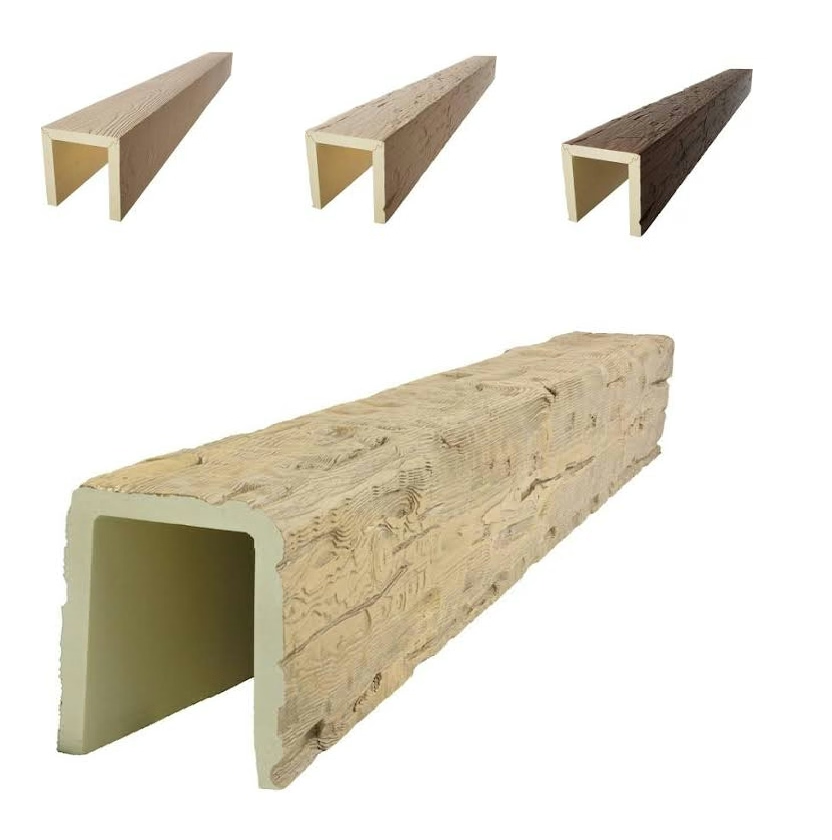
Outside corner connectors wrap the corner intersection, with each beam engaging a separate portion of the connector assembly. The connector must accommodate the beam profile accurately, maintaining consistent reveal and alignment across the corner transition. Quality connectors feature precision-formed surfaces that match specific beam profiles, ensuring consistent appearance throughout.
Supporting beam ends at outside corners requires attention to cantilever loads that the connection must resist. Unlike inside corners where beams support each other through the corner joint, outside corners require independent support for each beam's free end. Mounting systems must provide adequate resistance to downward loads and any torsional forces that might develop.
The visual termination point of beams at outside corners deserves consideration during planning. Some installations extend beams past the corner intersection, allowing the beam end to become a visible design element. Others terminate beams precisely at the corner, creating a clean geometric ending. Both approaches can achieve professional results when executed with appropriate attention to detail.
Three-Way and Four-Way Intersections
Complex beam layouts often involve three-way intersections where beams meet at a single point, or four-way intersections common in grid or coffered ceiling designs. These configurations require specialized connectors designed to accommodate multiple beam orientations simultaneously.
Three-way connectors typically feature a central junction point with arms extending at appropriate angles to receive each beam. The configuration may involve right angles for perpendicular intersections or other angles as project geometry requires. Installers must position the connector precisely, as any misalignment becomes visually apparent in the finished installation.
Four-way intersections commonly occur in grid patterns where beams cross at regular intervals. These installations often utilize simple crossing plates rather than complex multi-way connectors, with beams cut and fitted to interlock at the intersection points. The interlocking approach creates continuous appearance across both beams while simplifying inventory requirements.
Hybrid systems combining multiple connector types address unusual intersection configurations that standard connectors cannot accommodate. Experienced installers may fabricate custom solutions using standard hardware and careful measurement, creating connector arrangements that meet specific project requirements while maintaining professional appearance.

Connector Finishing and Concealment
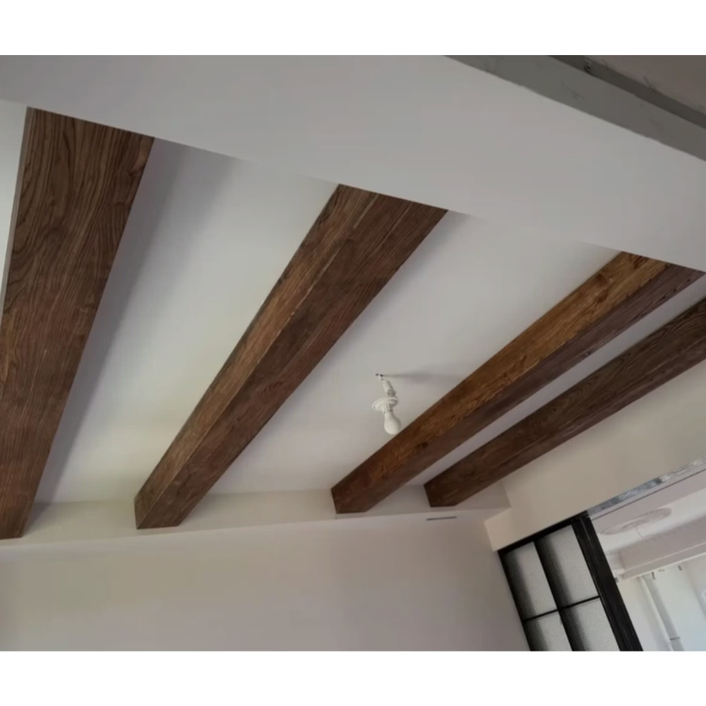
Concealing connectors represents a key objective in most installations, as visible hardware undermines the continuous wood appearance that beam installations seek. Proper technique ensures that connectors disappear within the finished assembly, creating the impression of solid wood construction.
Dry-fit verification before adhesive application allows installers to identify any gaps or alignment issues before commitment. The dry-fit process involves positioning all components without fastening, checking how beams meet at corners and whether connector engagement appears proper. Issues discovered during dry-fit can be addressed through adjustment, while issues discovered after fastening require corrective removal.
Adhesive application at corner joints creates bonds that reinforce mechanical connections while eliminating gaps. Polyurethane-compatible adhesives provide flexible bonds that accommodate the minor movements that temperature changes produce. Applying adhesive to both mating surfaces before joining ensures complete coverage and strong bonds.
Sanding and finishing may be necessary at corner joints to achieve seamless appearance. Minor gaps can be filled with wood filler or caulk matching the beam finish, then sanded smooth for invisible repair. The workability of polyurethane simplifies finishing at joints, as the material sands readily without tear-out or splintering.
Troubleshooting Common Corner Issues
Gap formation at corners typically results from dimensional variation between beams or improper cutting. Addressing gaps involves identifying their cause and implementing appropriate corrections. Beam dimensional issues may require replacement of affected pieces, while cutting problems can be corrected by recutting to proper angles.
Alignment discrepancies at corners often trace to ceiling backing placement that differs from expectations. When backing falls in unexpected locations, connectors may not engage properly, leading to misalignment that affects both appearance and structural performance. Adding supplementary backing at proper locations addresses this issue.
Connector failure, while uncommon with quality hardware, can occur under unusual stress conditions. Signs of connector failure include sagging at corners, visible movement when beams are pressed, or separation at joints. Addressing connector failure requires exposing the joint, replacing the failed hardware, and reinstalling beams with proper support.
Water damage to connectors can compromise performance in humid environments or where condensation occurs. Metal connectors may corrode, while adhesive bonds may weaken. Using moisture-resistant connectors and ensuring adequate ventilation prevents moisture-related problems that would otherwise develop over extended service periods.
Selecting Appropriate Connectors
Connector selection should match beam profile and installation requirements. Different beam widths and depths require corresponding connector sizes, and attempting to use undersized connectors creates performance and appearance problems. Manufacturers typically specify compatible beam profiles for each connector type.
Material compatibility affects connector selection for special applications. Standard steel connectors suit most interior installations, but marine or exterior applications may require stainless steel or coated hardware that resists corrosion. Chemical exposure or unusual environmental conditions may necessitate specialty connectors designed for specific challenging conditions.
Load requirements influence connector strength specifications. Beams spanning long distances or supporting additional weight require connectors rated for higher loads than those adequate for simple decorative installations. Verifying that selected connectors meet or exceed anticipated loads ensures safe, stable installations that perform reliably.
Warranty considerations may affect connector specifications for commercial applications. Some manufacturers require specific connector systems for warranty coverage, while others accept equivalent alternatives. Reviewing warranty requirements during specification prevents claim issues that might arise from using non-approved hardware.
Technical References
ASTM standards cited in every specification
Test Data
Lab results from internal testing program
Updated 2026
Reviewed against current product specs


