When interior designer Amanda Reyes specified twelve-foot faux beams for a forty-foot great room, she knew the math didn't work. No manufacturer offered standard twelve-foot beams that would span the entire length without visible interruption. The solution involved careful splicing—joining beam sections to create continuous runs that appeared seamless from below. Understanding how to splice beams properly enables installations that achieve spans beyond any single beam length.
Splicing polyurethane beams transforms what appears to be a limitation into a design opportunity. Strategic joint placement creates visual rhythm, while proper technique ensures that spliced installations perform as reliably as single-piece spans. The key lies in understanding splicing methods, joint reinforcement, and finishing techniques that make spliced beams appear continuous.
When Splicing Becomes Necessary
Many installations require splicing simply because available beam lengths cannot span required distances. Room dimensions frequently fall between standard length options, making splicing essential for achieving complete coverage without awkward gaps or exposed beam ends. Understanding when splicing is necessary helps plan installations that accommodate real-world dimensional constraints.
Design considerations sometimes create splicing requirements beyond what dimensional limitations impose. Beams that change direction, intersect with other beams, or pass through architectural features may require splicing that enables these configurations. While single-piece beams would simplify these transitions, practical availability makes splicing the realistic approach for most installations.
Architectural detailing can incorporate splices deliberately as design features. Joints positioned at regular intervals create rhythm that some design styles embrace rather than conceal. In these applications, the splice becomes a visible element acknowledged in the design rather than a technique to hide. Understanding the design intent guides whether splices should be concealed or featured.
Cost optimization sometimes favors splicing over custom-length ordering. While custom lengths eliminate splicing, they typically carry premium pricing and extended lead times. For projects with limited budgets or tight schedules, splicing standard-length beams may be more practical than pursuing custom options.
Splicing Joint Types
Different joint configurations serve different purposes and achieve different visual effects. Selecting the appropriate joint type for the specific application ensures that spliced installations meet both structural and aesthetic requirements.
The scarf joint represents the traditional woodworker's approach to joining beams end-to-end. Mating ends are cut at matching angles—typically thirty degrees or steeper—creating overlapping surfaces that blend when assembled. The long glue surfaces provide substantial bonding area, while the angled profile creates a gradual transition that hides the joint visually. Scarf joints work well when the joint will be visible, as the gradual angle transition appears intentional rather than apologetic.
The butt joint provides the simplest splicing approach, with beam ends meeting directly without angular preparation. While easier to cut and assemble than scarf joints, butt joints rely on smaller glue surfaces and create abrupt transitions that prove difficult to conceal. Butt joints work acceptably when hidden behind brackets, within hollow spaces, or in locations where appearance is irrelevant.
The finger joint employs interlocking projections that increase bonding surface area while providing mechanical interlocking that reinforces the connection. The complex profile creates significant glue surface while the interlocking geometry resists shear loads that might otherwise separate the joint. Finger joints work well in visible locations where their deliberate appearance can be treated as architectural detail.
The bridge joint utilizes a separate bridging piece that spans the joint from both sides, creating a reinforced connection that transfers loads across the splice location. The bridging piece—typically matching beam material—provides additional material at the joint that reinforces against bending and shear. Bridge joints prove particularly valuable for beams supporting additional weight.

Joint Reinforcement Methods
Mechanical reinforcement ensures that spliced joints maintain integrity under load and over time. Even the best adhesive bonds benefit from mechanical reinforcement that provides redundancy against failure modes that adhesive alone cannot address.
Steel plate reinforcement embeds metal plates within or across the joint to provide structural continuity. The plates extend beyond the joint on both sides, with fasteners engaging both the plate and beam material to create composite action. This approach provides substantial reinforcement while remaining concealed within the beam profile.
Biscuit joints employ compressed wood biscuits that fit into slots cut into both beam ends. The biscuits expand with adhesive, creating a mechanical interlock that supplements adhesive bonding. While less substantial than metal reinforcement, biscuit joints provide adequate reinforcement for most residential applications while remaining completely concealed.
Rod reinforcement utilizes threaded rods or dowels that extend through the joint from both sides. The rods engage both beam sections, providing mechanical continuity that adhesive bonds alone cannot match. Rod ends can be concealed with plugs matching beam material, creating joints invisible from normal viewing angles.
Bracket reinforcement positions metal brackets at joint locations, with the brackets engaging both beam sections through mechanical fastening. This approach provides visible reinforcement that some installations incorporate as design features. Industrial or rustic aesthetics may embrace visible bracket reinforcement, while more refined installations may require concealment.
Achieving Seamless Appearance
Concealing spliced joints requires attention to detail during both cutting and finishing. The goal involves creating joints that are invisible from normal viewing distances, maintaining the appearance of continuous construction that beam installations seek.
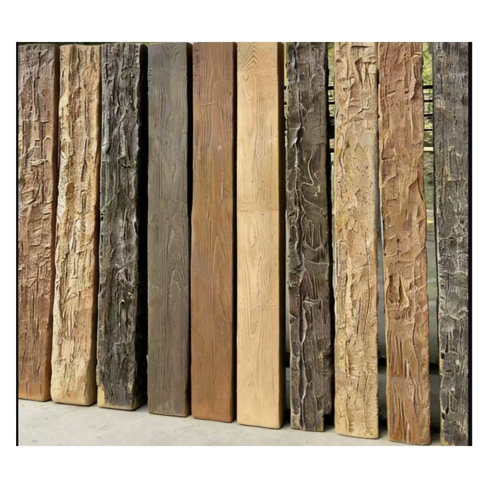
Matching grain patterns across the joint creates visual continuity that hides the splice location. When possible, orienting beam ends so that grain patterns align—as they would in continuous timber—produces natural transitions. This orientation requires planning during material ordering and selection, as it influences which beam ends should be cut for specific joints.
Color matching between beam sections ensures that spliced joints do not create visible color discontinuities. While factory-finished beams should match within production runs, beam sections from different batches might show slight color variations. Selecting beams from the same production run when possible, or ordering all beams for a specific run simultaneously, minimizes matching problems.
Finish application after splicing unifies appearance across joint locations. The finish applied to exposed joint surfaces should match factory finishes, with application techniques that blend seamlessly with adjacent surfaces. Light sanding between finish coats creates transitions invisible to casual observation.
Lighting considerations affect how successfully spliced joints can be concealed. Direct lighting perpendicular to beam runs casts shadows that emphasize surface irregularities including joints. Indirect or angled lighting tends to minimize joint visibility by reducing shadow formation. Understanding how room lighting interacts with beams guides joint placement decisions.
Planning Joint Placement
Strategic joint placement affects both structural performance and visual appearance. Thoughtful positioning ensures that splices contribute to overall installation quality rather than creating weakness or distraction.
Positioning joints at bracket locations provides mechanical support that splices benefit from. Bracket hardware reinforces the joint against loads that might otherwise stress the adhesive bond. Where possible, arranging for bracket locations to coincide with joint positions improves structural performance while hiding reinforcement requirements.
Staggering joints between adjacent beams prevents the visual rhythm that identically-positioned joints create. When multiple parallel beams require splicing, positioning joints at different locations along each beam creates variety that reads as intentional rather than repetitive. This staggering requires coordination during layout planning but produces more sophisticated visual results.
Locating joints away from primary viewing angles improves apparent seamlessness. Joints positioned where ceiling meets wall, or at room corners, disappear into architectural transitions more readily than joints in the center of visible ceiling planes. This positioning requires planning during layout but pays dividends in improved appearance.
Avoiding joints at stress concentrations prevents problems that would manifest over time. Joints positioned at mid-span locations experience higher bending moments than those near supports. Positioning joints closer to bracket locations reduces stress and improves long-term joint performance.
Quality Control and Testing
Verifying spliced joints before permanent installation ensures that connections meet requirements. Testing procedures identify problems that correction before mounting is far easier than repair after fastening.
Pull testing applies controlled force to joints before installation, verifying that adhesive bonds and reinforcement achieve expected strength. While formal pull testing requires equipment, simple hand pressure can identify obviously weak joints that would benefit from re-gluing or additional reinforcement.
Visual inspection examines joint surfaces for gaps, misalignment, or other defects before assembly. Identifying these issues during preparation enables correction, while discovering them after fastening may require disassembly that damages both beams and adhesive bonds.
Adhesive cure verification ensures that bonds have reached adequate strength before proceeding with installation. Premature handling of inadequately cured joints can weaken or break bonds. Following manufacturer cure time recommendations, extended if conditions are cool or humid, ensures that adhesive develops full strength.
Documenting joint locations assists with future maintenance or modification. Recording where splices occur, including photographs showing joint details, provides information that future work may require. This documentation proves particularly valuable for commercial installations where maintenance staff may need to locate or access spliced locations.
Technical References
ASTM standards cited in every specification
Test Data
Lab results from internal testing program
Updated 2026
Reviewed against current product specs


