U-shape polyurethane beams offer distinctive design possibilities that solid beam profiles cannot achieve. The hollow profile creates visual depth while reducing weight and enabling utility routing through the beam interior. Installing these beams requires attention to techniques specific to their unique construction, ensuring that results capitalize on the design advantages this profile offers.
The three-sided U configuration means these beams lack the continuous back surface that solid beams provide. Installation approaches must accommodate this characteristic, securing the beam through its side walls and flanges rather than through a single back plane. Understanding how to work with this profile ensures installations that perform reliably while showcasing the U-shape aesthetic.
Understanding U-Shape Beam Construction
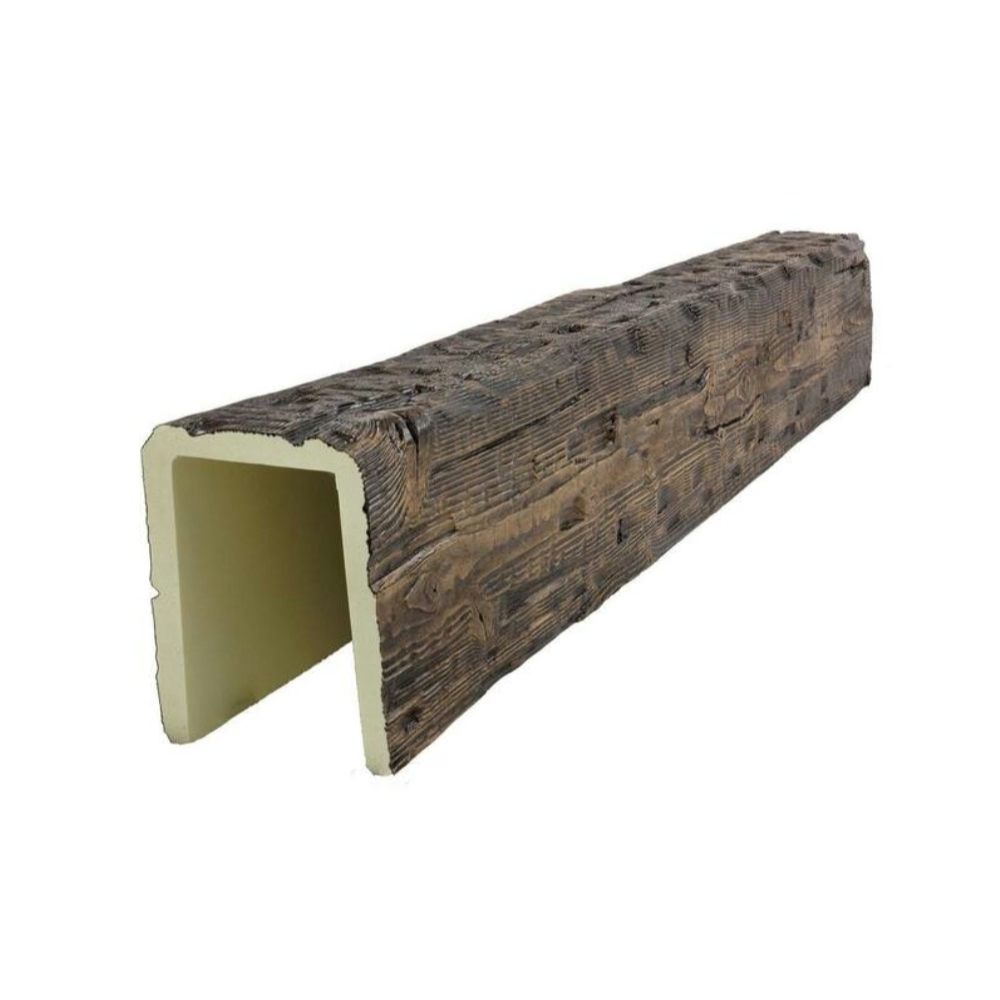
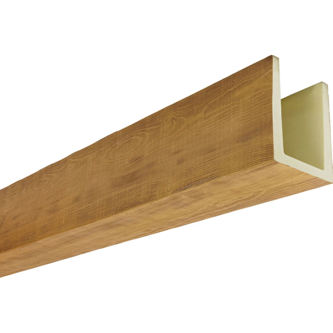
U-shape beams consist of three connected faces: a back panel and two side walls that extend forward to create the characteristic U profile. This construction produces a hollow interior that varies in size based on beam dimensions and wall thickness. The interior space can accommodate electrical wiring, low-voltage cable, and even small HVAC duct runs in some configurations.
Wall thickness in U-shape beams varies by manufacturer and product line. Thicker walls provide enhanced durability and better screw-holding capacity but increase weight and cost. Thinner walls reduce weight and cost but may require more careful handling and mounting to prevent damage. Understanding the specific wall thickness of your beams guides installation technique selection.
The interior cavity presents both opportunities and challenges. Routing utilities through the beam can simplify installation of lighting fixtures, speakers, or other ceiling-mounted items. However, the hollow construction also means that fasteners must engage properly with the material without penetrating through visible surfaces. Careful fastener selection and technique prevents damage while providing adequate holding power.
The open front of the U-shape creates a visual shadow line that contributes to the beam's dimensional appearance. This shadow effect enhances realism by suggesting actual depth rather than flat surface. Maintaining this shadow line during installation—ensuring that beams are level and properly positioned—preserves the dimensional character that distinguishes U-shape profiles.
Preparation Before Installation
Thorough preparation ensures that installation proceeds smoothly and produces quality results. Taking time to prepare the work area, verify beam conditions, and organize materials prevents the delays and frustrations that disorganized work creates.
Beam inspection upon delivery identifies any shipping damage that might affect installation or appearance. Checking for cracks, dents, or surface blemishes while materials are still on hand enables prompt replacement of damaged pieces. Documenting damage with photographs supports warranty claims if manufacturers require evidence of shipping-related issues.
Conditioning beams to ambient temperature and humidity reduces dimensional changes that might occur after installation. While polyurethane is more dimensionally stable than natural wood, extreme temperature differences between storage and installation environments can create minor fitting issues. Allowing beams to acclimate in the installation space for twenty-four to forty-eight hours before installation promotes stable dimensions.
Organizing mounting hardware and tools prevents installation interruptions that costly delays would create. Separating hardware by type and location, verifying quantities against requirements, and staging tools within easy reach creates workflow efficiency. This organizational investment pays returns throughout the installation process.
Test fitting beams before committing to installation identifies any clearance issues or dimensional conflicts. Checking how beams will sit against ceiling planes, align with adjacent beams, and engage with mounting hardware provides opportunities to address problems before permanent fastening. This dry-run approach prevents the frustration of discovering problems after adhesive application or fastener installation.
Mounting Techniques for U-Shape Profiles
U-shape beam mounting requires techniques adapted to the profile's unique construction. The mounting approach must secure the beam adequately while accounting for the hollow interior and the shadow line that defines the visual profile.
Back-mounting through the rear panel provides primary support in many installations. This approach involves driving screws or bolts through the beam's back wall into structural ceiling elements or mounting blocks. The screw-holding capacity of polyurethane, while adequate for reasonable loads, benefits from using screws with coarse threads that engage material effectively.
Side-mounting techniques secure beams through the U walls when back access is limited. This approach requires longer fasteners that penetrate through side walls into structural backing behind. The fastener angles necessary for side mounting may require predrilling to prevent cracking, with bit size slightly smaller than fastener shank diameter.
Internal support systems utilize the hollow interior for mounting hardware placement. Steel angle brackets or channels positioned inside the beam create attachment points that remain hidden after installation. This approach provides strong mechanical connections while maintaining the appearance of solid timber construction. Internal mounting requires coordination during ordering to ensure that internal hardware arrives with beams.
Combination mounting that layers multiple attachment methods provides the strongest installations for demanding applications. Using both mechanical fastening and adhesive bonding creates redundant attachment that ensures performance even if one attachment method fails. This approach suits commercial applications or situations where beams will experience unusual stress.

Achieving Proper Alignment
Alignment precision determines whether U-shape beams read as quality craftsmanship or amateur installation. The consistent dimensional appearance of U-shape profiles means that any misalignment becomes immediately apparent, making careful positioning essential for professional results.
Reference lines establish alignment baselines that guide entire installations. A chalk line or laser level reference along the ceiling plane marks the centerline that each beam should follow. Measuring from this reference rather than estimating from walls or corners prevents cumulative positioning errors that would create visible crookedness.
Temporary support systems hold beams in position during alignment and fastening. Adjustable ceiling hooks, removable adhesive products, or simple bracing all serve this purpose. The goal involves freeing both hands for accurate bracket installation and secure fastening while maintaining the precise positioning that alignment requires.
Checking alignment from multiple viewing angles reveals problems that single viewpoints might miss. Walking around installed sections while viewing from different directions identifies any inconsistencies. The three-dimensional nature of U-shape beams means that alignment problems can appear from some angles but not others, requiring comprehensive checking.
Sighting along beam runs identifies alignment problems between adjacent beams. Looking from one end of a beam run toward the other reveals whether beams track consistently or drift from the intended line. This technique catches alignment issues that measurement alone might miss, ensuring smooth visual flow throughout the installation.
Finishing and Sealing
Proper finishing protects beams while enhancing their dimensional appearance. Attention to details like joint sealing and edge finishing distinguishes professional installations from amateur efforts, creating the finished appearance that justifies the investment in quality beams.
Joint sealing at beam intersections prevents light from penetrating gaps that would be visible from below. Flexible sealant compounds appropriate for polyurethane create weatherstripping-like barriers that accommodate minor movement without cracking. Applying sealant before beam positioning, then tooling to proper profile, creates joints invisible from normal viewing angles.
Cut edge finishing maintains appearance at any field-cut locations. The end grain visible when beams are cut to length may absorb finish differently than molded surfaces, requiring attention to achieve consistent appearance. Priming cut edges before installation, then touching up after installation, ensures that any cut surfaces match finished appearance.
Cleaning after installation removes fingerprints, dust, and installation debris that accumulate during the mounting process. Polyurethane-safe cleaners remove contamination without damaging surfaces. Testing cleaners on inconspicuous areas before broad application prevents potential damage to visible surfaces.
Protective coating application may be appropriate for some installations. While many beams arrive pre-finished from manufacturers, additional topcoat application can enhance durability in demanding environments. Consulting with manufacturers about compatible coating products ensures that any additional finish will bond properly and provide intended protection.

Common Installation Mistakes to Avoid
Understanding common mistakes helps installers avoid problems that would compromise results. Learning from others' experiences proves more efficient than discovering issues through trial and error.
Insufficient support spacing creates sagging or stress concentrations that shorten beam life. Mounting brackets spaced too far apart allow beam weight to create deflection that becomes visually apparent and potentially damaging. Following manufacturer spacing recommendations, typically no more than four feet apart for standard installations, ensures adequate support.
Improper fastener selection leads to either inadequate holding power or visible surface damage. Screws that are too large crack polyurethane surfaces, while screws that are too small pull out under load. Selecting fasteners recommended by manufacturers or qualified contractors ensures appropriate engagement without damage.
Skipping the dry-fit step creates problems that become apparent only after permanent installation. Discoveries that beams don't align properly, brackets don't engage as expected, or clearances are inadequate require corrective work that damages both beams and installation quality. The time invested in dry-fitting prevents these costly corrections.
Inadequate sealing at joints and penetrations allows moisture intrusion that affects both beams and building structure. Water entering beam interiors creates conditions for mold growth and material degradation that may not become apparent until significant damage has occurred. Thorough sealing during installation prevents these problems throughout the service life of the installation.
Technical References
ASTM standards cited in every specification
Test Data
Lab results from internal testing program
Updated 2026
Reviewed against current product specs


