A U-shaped beam arrangement—one where beams run along two adjacent walls and connect at the corner—creates one of the most dramatic ceiling treatments available with faux wood beams. The geometry turns a flat ceiling into a framed composition, defining the room's architecture and drawing the eye upward. But corners are where amateur installations fall apart, literally. A poorly executed corner joint looks like what it is: two pieces of foam cut at an angle and held together with hope. A properly executed corner looks like a single piece of timber that was crafted to fit the room exactly.
The difference lies in understanding the geometry of the corner, planning the cuts carefully, and using the right reinforcement techniques.
Understanding Corner Geometry
Before you cut anything, you need to understand what kind of corner you're working with. Interior corners—the ones inside the room, where two walls meet at a right angle—are the most common. Exterior corners—where the room turns outward—are less common but require different treatment.
For interior corners, the challenge is that the two beams approaching the corner are traveling in perpendicular directions, and each one needs to be cut so that it meets the other cleanly along a forty-five-degree miter. But here's the catch: a standard forty-five-degree miter cut on two beams of equal depth produces a corner that looks correct from directly below but reveals a visible gap when viewed from an angle. This is because the end grain of the beam—the cut face—has depth, and at a mitered corner, the two end grains meet along a line rather than overlapping.
To visualize this, consider two beams of equal width and depth meeting at a right interior corner. If you cut both at forty-five degrees and push them together, the end grain faces meet along a single line that runs diagonally across the corner. From directly below, this looks perfect. From any other angle, you can see the seam because one end grain plane is visible in front of the other. The solution is to use a coped joint rather than a miter for the connecting beam.
The Coped Joint Approach
A coped joint addresses the end-grain visibility problem by cutting the end of one beam—the connecting beam that runs along the secondary wall—at an angle that follows the profile of the first beam, rather than cutting both beams at matching forty-five-degree angles.
To make a coped joint, first cut the beam that will sit along the primary wall—the one that forms the corner's inside face—at a forty-five-degree angle. This is your reference piece. Then, trace the profile of the first beam's end grain onto the end of the second beam using a pencil. This trace follows the beam's contour—the curved or shaped profile of its decorative face—rather than a simple diagonal line. Cut along that traced line with a jigsaw or band saw, producing a shape that interlocks with the end of the first beam.
When assembled, the coped joint shows no end grain from most viewing angles because the coped end of the second beam wraps around the end grain of the first. The seam follows the contour of the beam's decorative face rather than a straight diagonal line, making it far less visible.
For U-shaped arrangements that continue around two walls and back toward a single point, you'll need one mitered joint and one coped joint per corner. The mitered joint goes on the beam that turns the corner and will be visible only from below. The coped joint goes on the beam that returns along the adjacent wall and is visible from the room.
Making the Cuts
Accurate cuts are essential for a clean corner. Use a miter saw for forty-five-degree cuts on the mitered joint—it produces the cleanest, most consistent angle. Set the saw to forty-five degrees and cut the beam from the back face toward the front face, so the decorative front face remains uncut. This keeps the visible surface pristine and moves the saw cut to the less visible end grain.
For coped cuts, a jigsaw or band saw gives you the control needed to follow a curved or profiled line. Mark the cut line carefully using a pencil and a flexible curve or by tracing directly from the mitered beam's end grain. If the beam has a simple rectangular profile, you can cut a forty-five-degree angle and then square off the corner with a chisel or rasp to simulate a cope. For beams with routed details, you need to follow the profile precisely.
Take your time with the coped cut. It's better to cut slightly outside the line and refine the fit with sandpaper or a rasp than to cut inside the line and have to fill a gap. Test-fit both pieces in the corner before applying any adhesive. The coped end of the second beam should seat snugly against the mitered face of the first, with no gaps wider than a sixteenth of an inch.
Reinforcing the Corner Joint
Adhesive alone is not sufficient for corner joints, especially in ceiling installations where gravity is constantly pulling on both beams. The joint needs mechanical reinforcement. The method depends on the type of beam—hollow or solid—and the available surfaces for fastening.
For solid polyurethane beams, drive two or three wood screws through the back of the mitered beam into the end grain of the coped beam. Pre-drill the screw holes and countersink them so the screw heads sit below the surface. The screws should be sized so they don't protrude through the front face of the coped beam. Two-and-a-half-inch wood screws typically work well for most beam depths.
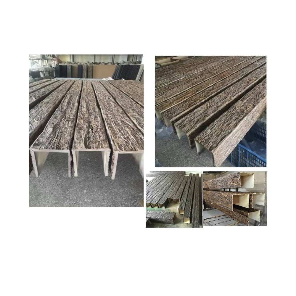
For hollow beams, you need to create a solid backing behind the joint. Cut a piece of one-by lumber or plywood to fit inside the hollow of each beam at the corner—approximately six inches long for each beam arm. Slide these backing pieces into the hollow cores of both beams so they extend into the corner overlap zone. Then apply adhesive to both the backing pieces and the mating surfaces of the beams, and drive screws through the beam walls and into the backing blocks. This creates a solid composite joint that resists the shear and rotational forces that loosen mitered corners over time.
For U-shaped arrangements that wrap around an exterior corner, the approach changes. An exterior corner requires the beams to turn outward, which means the end grains are exposed to the room. In this case, a mitered joint on both beams—cut at forty-five degrees in opposite directions—produces a clean corner that looks like the outside of a picture frame. Reinforce with screws driven through the mitered faces and into a backing block that spans the corner inside both beams.
Assembling and Installing the U-Shape
Once the corner joints are cut and reinforced, assemble the U-shape on the floor before lifting it into place. This dry-run assembly lets you verify that all joints fit correctly and that the overall dimensions match your planned layout. Make any final adjustments to the coped cuts while the pieces are on the ground—it's far easier than working overhead.
Apply adhesive to all mating surfaces—the back of the mitered joint, the cope profile of the second beam, and any exposed end grain. Clamp the joints together using bar clamps or pipe clamps, and allow the adhesive to cure fully before moving the assembled U-shape. A minimum of two hours for the adhesive to set and twenty-four hours to fully cure is a safe guideline.
Lift the assembled U-shape into position and mount it using your planned ceiling fastening method—blocking and screws, direct-to-joist attachment, or adhesive with supplemental screws. Begin by attaching the corner joint itself, driving screws through both beams into the ceiling blocking at the corner. Then work outward along each arm, securing the beams at their attachment points.
After installation, fill any visible gaps at the joints with paintable caulk, and touch up any minor finish imperfections with stain or paint. The goal is a U-shaped beam frame that looks like it was milled from a single piece of timber and installed as a unit.

Corner junctions are the most technically demanding part of any multi-beam installation, but with careful cutting, proper reinforcement, and patient assembly, they can be executed to a standard that elevates the entire project. A well-built corner joint doesn't just look better—it lasts longer, resisting the forces that cause lesser installations to develop cracks and gaps within the first year.
Technical References
ASTM standards cited in every specification
Test Data
Lab results from internal testing program
Updated 2026
Reviewed against current product specs


