
Long spans present faux beam installations with a fundamental challenge: standard beam lengths rarely match the full distance between support points. Where real timber might be sourced in lengths sufficient for uninterrupted spans, manufactured faux beams typically max out at twelve to sixteen feet, leaving installers to create field joints where beam sections meet.
These joints, if executed poorly, betray the manufactured nature of the beams and disrupt the continuous timber aesthetic that makes beam installations compelling. Interlocking beam systems address this challenge through thoughtful engineering, creating connections that disappear visually while maintaining structural integrity and simplified installation.
Understanding the Long-Span Challenge
Residential and commercial spaces frequently require beam spans exceeding available standard lengths. A great room spanning thirty feet needs either single-piece beams—expensive and difficult to transport—or multiple sections joined in the field. Field joints create several potential problems that interlocking systems solve.
Visible seams disrupt the continuous wood appearance that beam installations aim to achieve. Even well-executed joints catch light differently than surrounding beam surfaces, creating lines that catch the eye and announce themselves as manufactured interruptions. Poorly executed joints become maintenance concerns as they may separate, crack, or collect debris over time.
Structural concerns arise when joints rely on inadequate support. Real timber beams transfer loads continuously across their entire length; faux beams must create load paths that function similarly despite manufactured discontinuities. Improperly supported joints may sag over time, creating visible deflection that compounds aesthetic problems with functional failure.
Principles of Effective Beam Interlocking
Effective interlocking systems address both aesthetic and structural requirements through complementary approaches. The visual system creates seamless appearance through careful profile matching, alignment precision, and finishing techniques that blend joint locations. The structural system transfers loads through robust connection methods that prevent deflection and maintain alignment over time.
Aesthetic interlocking depends on profile continuity across the joint location. The male and female profiles must mate precisely, with no step, gap, or dimensional variation visible after installation. This precision requires either factory-engineered interlocking profiles or meticulous field preparation for universal profile types.
Structural interlocking distributes beam loads across multiple support points rather than concentrating them at joint locations. This load distribution prevents the joint from becoming a structural weak point while allowing minor movement flexibility that accommodates environmental factors like temperature-induced expansion and contraction.
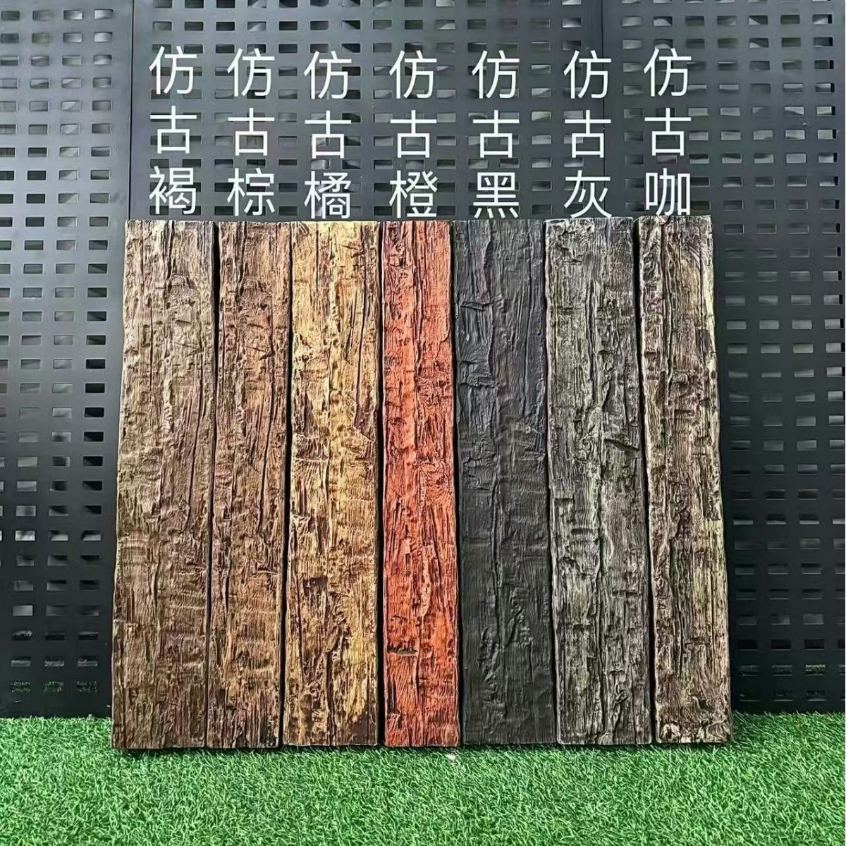
Tongue-and-Groove Interlocking Systems
The most common interlocking approach adapts the centuries-old tongue-and-groove joinery used in wood flooring and paneling. A protruding tongue on one beam section seats into a corresponding groove on the adjacent section, creating alignment and load transfer simultaneously.
Factory-produced tongue-and-groove profiles ensure dimensional consistency that field-machined profiles cannot match. When ordering beams with factory interlocking, specify joint locations precisely so tongue and groove elements arrive oriented correctly for the intended installation sequence. Mixing orientation—installing a groove-side next to another groove-side—creates problems that require field correction.
Installation proceeds from one end of the span toward the other, engaging each tongue into its corresponding groove as beam sections are positioned. This sequential engagement prevents the joint from locking up prematurely and allows adjustment until the beam is fully seated. Adhesive applied to mating surfaces provides additional security and helps fill any microscopic gaps that might allow light penetration.
The primary limitation of tongue-and-groove interlocking is its inherent weakness when loaded perpendicular to the joint. The tongue provides alignment but limited bearing surface for vertical load transfer. Additional support methods—brackets, straps, or blocking—may be required for spans with significant loads or reduced support point availability.
Scarf Joint Systems for Enhanced Strength
Scarf joints—ancient in woodworking tradition—create longer, angled glue surfaces that distribute loads more effectively than perpendicular butt joints. A forty-five-degree angled cut on each beam end produces matching surfaces that interlock when the beams are drawn together.
The angled geometry provides substantially more glue surface than perpendicular cuts, increasing joint strength significantly. Scarf joints also hide better than butt joints because the angled transition creates less pronounced visual interruption. When light rakes across a scarf joint at shallow angles, the transition follows the grain direction and remains less visible than perpendicular seam lines.
Factory scarf-cutting produces cleaner results than field cutting, particularly for long or complex angles. Specify scarf angles that maximize glue surface while remaining manufacturable—typically between thirty and sixty degrees from perpendicular. Steeper angles increase glue surface but become more difficult to cut and clamp accurately.
Scarf joints require careful clamping during adhesive cure to maintain alignment. Temporary bracing or specialized clamping jigs hold beam sections in precise alignment while adhesive sets. Rushing this clamping phase invites misalignment that becomes permanent when adhesive cures, so build adequate cure time into installation scheduling.
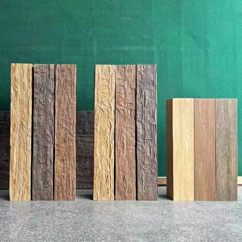
Cam Lock and Mechanical Fastening Systems
Modern engineering has produced mechanical fastening systems that supplement or replace traditional adhesive-only joints. These systems use proprietary hardware—cams, locks, pins, or clips—to create immediate mechanical engagement while adhesive provides long-term security.
Cam lock systems employ rotating mechanisms that draw beam ends together and lock them in position. Installation requires simply engaging the mechanism and rotating to lock, providing consistent results without the skill dependency of traditional joinery. Disassembly capability also benefits maintenance scenarios where beam access becomes necessary.
Pin and clip systems use multiple small connectors distributed across the joint surface rather than single large fasteners. This distributed approach reduces stress concentration at any single point while providing multiple load paths. The smaller hardware remains largely concealed after installation, preserving the continuous wood appearance.
Evaluate load ratings for mechanical systems against project requirements. Some systems are engineered for light-duty applications where beams serve primarily decorative rather than structural purposes. Others provide load ratings suitable for substantial ceiling treatments where beam weight and any attached fixtures require robust support.

Support Integration at Joint Locations
Joint locations benefit from additional structural support beyond the interlocking mechanism itself. Supplemental support points reduce joint stress while maintaining the uninterrupted appearance that makes interlocking systems valuable.
Hidden bracket systems mount above the joint location, connecting both beam sections to ceiling structure through hardware that remains invisible from below. These brackets transfer load through the bracket rather than relying solely on the beam-to-beam connection, providing redundancy that protects against joint failure.
Support blocks positioned between beams at joint locations provide bearing surface for vertical loads. The blocks may be hidden within the beam structure, behind decorative trim elements, or positioned within the beam hollow if hollow-core profiles are used. Access for block installation must be considered during installation sequencing.
For very long spans or heavy beam installations, consider engineering consultation to verify that support strategies adequately address loads and deflection requirements. What appears adequate visually may not meet structural requirements, particularly in commercial applications or areas with seismic or wind load considerations.
Finishing Techniques for Seamless Appearance
Even structurally perfect joints can betray their location without appropriate finishing. Several techniques help blend joint locations into surrounding beam surfaces for genuinely seamless appearance.
Sanding and feathering smooths transition points where profiles meet. Use progressively finer abrasives to blend any minor height differences, feathering the edges of higher sections into surrounding surfaces. This process requires patience but produces results that cannot be achieved through hasty preparation.
Wood filler matched to beam finish fills any remaining gaps or imperfections. Select filler products that accept stain or paint in the same manner as the surrounding beam surface, and test application on scrap material before using on visible beam surfaces. Apply filler in thin layers, allowing each to cure before applying subsequent layers, to prevent cracking or shrinkage.
Stain and finish application should extend across the entire beam span rather than per-section to prevent color variation between separately finished pieces. Apply finish to complete beam runs after all joints have cured and been properly finished, treating the entire assembly as a single continuous surface.
Planning for Interlocking Assembly
Successful interlocking installation requires planning that begins during material specification and continues through installation execution. Several factors deserve attention before ordering or installation.
Calculate joint locations based on beam availability and support point positions. Ideal joint locations align with existing support structure—joists, beams, or added blocking—where additional support can be provided without visual compromise. Avoid placing joints in spans between supports unless structural reinforcement compensates for the reduced load path.
Sequence installation to allow access for joint assembly and finishing. The last section to be installed should be positioned so that its engagement with the previous section remains accessible for clamping, adhesive application, and alignment verification. This sequencing constraint may influence beam order specification.
Allow for dimensional tolerances across long spans. Building construction rarely achieves perfect precision over extended distances; beam lengths may need field adjustment to accommodate actual measured dimensions rather than nominal specifications. Build measurement time into installation scheduling so adjustments can be made without pressure.
Maintenance Considerations for Interlocking Systems
Interlocking joints, despite their robust initial installation, may require attention over time as buildings settle and environmental conditions fluctuate. Understanding maintenance requirements helps establish realistic expectations and appropriate inspection schedules.
Periodic inspection should verify that joints remain aligned and that no gaps have developed at joint locations. Small gaps can be filled with appropriate caulk or wood filler before they enlarge; larger gaps may indicate structural issues requiring more comprehensive remediation.
Temperature and humidity fluctuations cause building materials to expand and contract. In regions with significant seasonal variation, joints may show minor movement that is normal and expected. Document joint appearance at installation and compare during subsequent inspections to distinguish normal variation from problematic degradation.
Repair procedures for interlocking joints depend on the specific system and access available. Some joints can be disassembled for repair or replacement of damaged sections; others may require section removal and replacement if damage occurs. Understanding the repair implications of different systems helps inform system selection for specific applications.
When Interlocking Systems Excel
Interlocking beam systems provide particular advantages in specific contexts where their benefits outweigh any added complexity or cost.
Great rooms and open-plan spaces with long spans benefit most from seamless interlocking treatment. The continuous ceiling line these systems produce enhances the open feeling while providing the visual structure that prevents vast ceilings from feeling formless.
Commercial applications with extended sightlines—lobbies, restaurants, hospitality spaces—require the polished appearance that interlocking provides. Visible joints in these high-visibility applications compromise the professional image these spaces require.
Renovation projects where faux beams extend existing real timber framing benefit from interlocking systems that create continuity between old and new materials. The seamless joint helps the faux sections appear as natural extensions of the authentic structure rather than obviously manufactured additions.
By selecting appropriate interlocking approaches and executing installations with attention to detail, designers and installers can create long-span faux beam ceilings that achieve genuinely seamless appearance without sacrificing structural integrity or installation efficiency.
Technical References
ASTM standards cited in every specification
Test Data
Lab results from internal testing program
Updated 2026
Reviewed against current product specs


