
Picture yourself standing in a grand foyer where exposed timber beams stretch across a 50-foot ceiling, their grain patterns flowing uninterrupted from one end to the other. No seams interrupt the visual journey. No visible joints break the architectural rhythm. This is the power of interlocking joint design in modern polyurethane faux wood beam systems, a technology that has fundamentally changed what is possible in ceiling design and architectural woodwork.
The concept might seem simple on the surface—instead of cutting beam ends flat and butting them together, you create interlocking profiles that mesh precisely—but the engineering behind truly effective interlocking joints involves sophisticated mold design, tight manufacturing tolerances, and carefully formulated materials. When executed well, the result is a connection that rivals the appearance of single-piece timber while offering performance characteristics that natural wood simply cannot match.
The Engineering Behind Effective Joints
The traditional approach to extending wooden beams involves one of several methods: scarf joints cut at angles to increase glue surface area, splines inserted into matching grooves, or metal plates bolted through the beam ends. Each of these approaches has limitations when applied to the aesthetic requirements of exposed beam installations. Scarf joints remain visible. Splines create linear interruptions in the grain pattern. Metal hardware must be concealed or becomes an unwanted visual element.
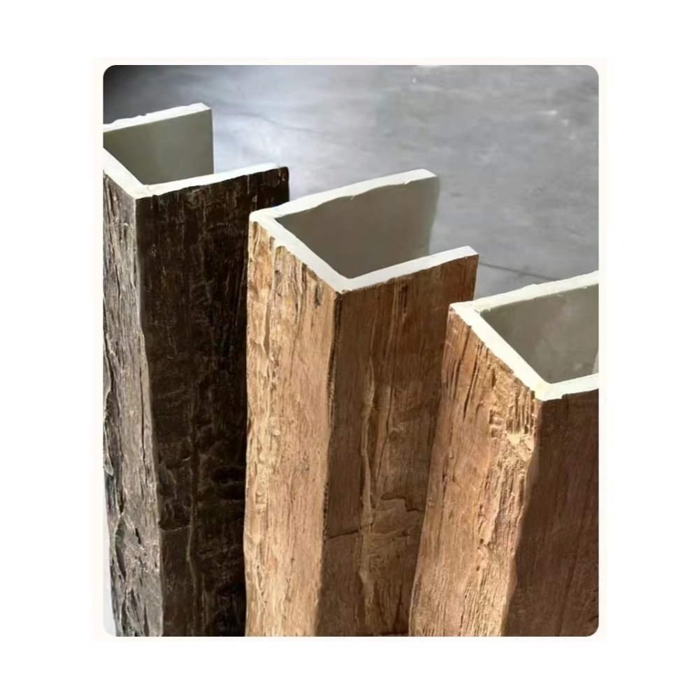
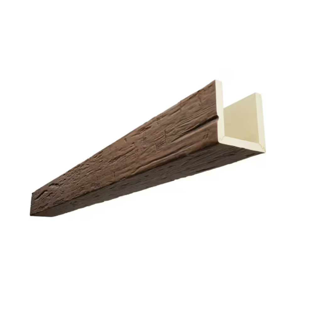
Interlocking joint design sidesteps these issues entirely by making the joint itself an integral part of the beam's profile. The male and female profiles that engage during installation are continuous along the beam's length, meaning that when two sections are joined, the profile geometry is identical to what exists elsewhere along the beam surface. There is no transition point, no change in the surface relief, no interruption in any visual element.
Modern PU faux wood beam manufacturers achieve this through precision injection molding or CNC machining processes that maintain consistent dimensions within tight tolerances. A beam designed for interlocking applications might specify that the male profile dimensions be held to within 0.5 millimeters across the entire production run. This consistency ensures that any beam section can be joined to any other section from the same product line, creating predictable results regardless of which pieces happen to be adjacent during installation.

Connection Geometry Options
Not all interlocking joint geometries are created equal, and understanding the differences helps designers and installers make informed decisions about which systems best suit their project requirements. Several distinct approaches have emerged as industry standards, each with particular strengths.
The simple tongue-and-groove configuration represents the most straightforward interlocking approach. One beam carries a protruding tongue along its edge while the adjacent beam features a matching groove. Assembly is intuitive, requiring only alignment and sliding the beams together. While effective for shorter runs and applications with minimal stress on the joints, pure tongue-and-groove geometry may require additional mechanical reinforcement for critical long-span applications.
More sophisticated interlocking profiles incorporate multiple engagement points along their edges. These compound geometries might feature a primary structural interlock that handles load transfer between beam sections, supplemented by secondary sealing surfaces that ensure tight contact across the entire joint width. Some manufacturers employ asymmetrical profiles that only allow assembly in one orientation, which can actually benefit installation by preventing accidental reversed installation.
The most advanced interlocking systems add integral alignment features that guide the installer toward correct positioning as the beams approach each other. Chamfered entry edges, for example, gradually bring misaligned beams into proper registration as they are pushed together. These self-aligning features reduce installation skill requirements and help ensure consistent results across different installer experience levels.
Load Distribution and Structural Performance
A joint that looks perfect but fails under load represents a failure of the overall system. Premium interlocking PU faux wood beam designs address structural performance as a primary consideration, not an afterthought. The joint must transfer tension, compression, and shear forces between beam sections without allowing movement or separation.
Load distribution in interlocking joints occurs through several mechanisms working in concert. The mechanical interlock of the profiles provides primary resistance to separation forces, similar to how a mortise and tenon joint functions in traditional woodworking. Adhesive bonding between the closely fitted surfaces provides secondary reinforcement and helps distribute stress across the joint interface. The inherent stiffness of the PU material itself contributes to overall system rigidity.
Engineered interlocking joints typically exceed the shear strength of the surrounding beam material. This means the joint is actually stronger than a single beam section would be at the same cross-section. The safety margin built into these connections provides confidence for demanding applications, including multi-layer beam installations where beams are stacked or combined with structural hardware.
Thermal movement presents a particular challenge for any jointed beam system. Natural wood expands and contracts with changes in humidity and temperature, and these dimensional changes can stress joints over time. PU faux wood beams exhibit substantially lower thermal expansion coefficients than natural timber, meaning the differential movement between adjacent beam sections is minimal. This dimensional stability translates directly into long-term joint integrity.
Professional Installation Techniques
Achieving flawless interlocking beam runs requires more than simply sliding pieces together. Professional installers develop techniques and workflows that optimize both the visual outcome and the structural performance of the finished installation.
Planning the layout before any adhesive is applied represents the most important pre-installation step. This involves measuring the total run distance, accounting for any corners or obstructions, and calculating how beam sections will divide across the entire length. Professional installers often create a scale drawing or template that shows exactly where each joint will fall, allowing them to optimize piece placement for minimal waste and maximum visual continuity.
Cutting and trimming of beam sections should occur before adhesive application. While interlocking profiles are precision-molded, beam ends that require cutting for length should be cut square and cleanly to ensure proper engagement with the next section. Any factory finishes or textures should be maintained across cut surfaces by using sharp blades and appropriate cutting techniques.
Adhesive application deserves careful attention. The surfaces of interlocking profiles should be clean, dry, and free of any contamination that might inhibit bonding. Adhesive should be applied to both surfaces being joined, typically using a serpentine or zigzag pattern that ensures complete coverage while avoiding excess material that might squeeze out during assembly. Some installers prefer to apply adhesive to one profile, then "dry fit" the joint before making the final bonded connection, allowing them to verify alignment before committing to the joint.
Clamping the joint during adhesive cure provides insurance against movement that could compromise the bond. While many interlocking geometries are self-aligning and resist separation, the adhesive bond itself benefits from undisturbed curing. Simple bar clamps or strap clamps positioned near the joint work well for most applications and can be removed once the adhesive reaches adequate green strength.
Design Integration and Finish Considerations
Interlocking joints must not only perform structurally but integrate seamlessly into the overall design vision. The best interlocking systems achieve this integration so completely that the joint line becomes invisible to casual observers, even when they know exactly where to look.
Finish application strategy significantly influences joint visibility in the completed installation. When beams will receive site-applied stain or finish, the installer must ensure consistent finish application across both the molded beam surface and any cut surfaces at beam ends. This typically means applying finish to each beam section before assembly, then touching up any areas that might have been damaged during handling or installation. Alternatively, factory-finished beams arrive with uniformly applied coatings that require no site finishing, eliminating the challenge of matching finishes across joints.
In some design approaches, the interlocking joint is not hidden but celebrated as a design element. The joint geometry itself becomes part of the aesthetic, with specific profile designs selected to complement the overall style of the installation. Craftsman-style beams might feature stepped interlocking profiles, while contemporary designs might emphasize clean, geometric joint transitions.
The maintenance advantages of interlocking systems extend beyond initial installation. Should a section of beam ever require replacement due to damage, the interlocking joint can be disassembled and the affected section removed without disturbing the entire run. This selective repair capability represents a significant advantage over systems where individual sections cannot be accessed without destroying adjacent material.
Interlocking joint design has matured from a clever solution for difficult installations into a mainstream approach embraced by architects, designers, and builders who demand the absolute best in both appearance and performance. The technology continues to evolve, with newer systems offering improved aesthetics, easier installation, and enhanced structural capabilities that expand the range of possible applications even further.
Technical References
ASTM standards cited in every specification
Test Data
Lab results from internal testing program
Updated 2026
Reviewed against current product specs


