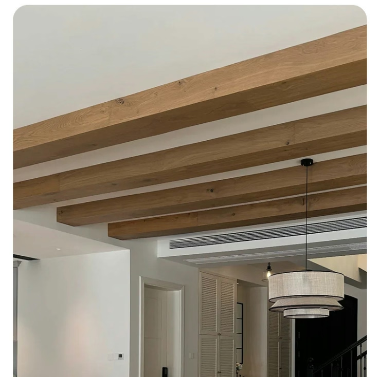
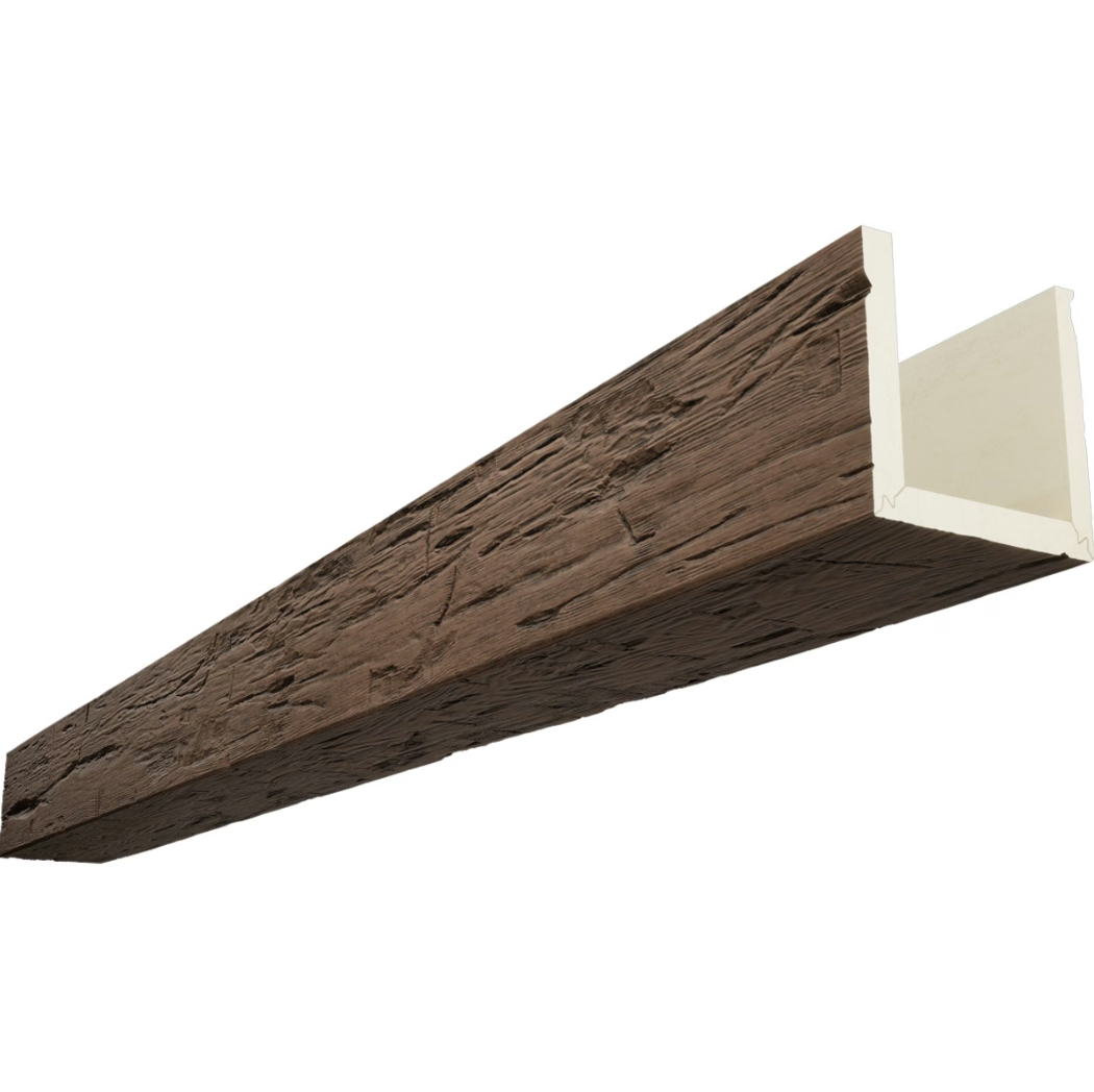
The architectural profession operates in a world of precise documentation. Construction drawings communicate design intent through dimensions, annotations, and symbols that contractors interpret to produce the built environment. When faux beams appear in these drawings, they enter a documentation ecosystem that expects exact specifications. A dimension specified as eight inches must translate to an eight-inch beam. A position marked at a given elevation must place the beam at exactly that height. Faux beams designed for construction document compatibility respect this expectation, bridging the gap between paper specifications and physical reality.
The specification process for beams intended to match construction documents begins with drawing review. The architect or specifier identifies all drawings where beam elements appear—plan views showing beam positions, elevation views showing beam profiles, section views detailing connections and intersections, and schedules listing beam quantities and dimensions. This review identifies potential conflicts or ambiguities before production begins, allowing corrections to be made on paper rather than discovered on the job site.
Cross-referencing between drawing types reveals the full scope of beam requirements. A plan view might show four beams running east to west at specified intervals, while elevation views reveal that these same beams must coordinate with windows, light fixtures, or ceiling conditions that the plan does not show. Section views may indicate connections to walls or structural elements that require special treatment. Only by examining all drawing types together can the complete specification be assembled.

Coordinate systems provide the framework for precise beam positioning. Construction documents typically reference a project coordinate system with established origin points and axes. Beam positions measured from these reference points translate directly to field measurements that installers can verify. When ordering beams, specifying the coordinate-based positions rather than relying on field estimation ensures that beam placements align with other building elements—walls, columns, windows, and mechanical equipment—that were also positioned using the same coordinate reference.
The dimension specification must account for how the beam relates to other building elements at connection points. An end condition where the beam meets a wall might show the beam as flush with the wall face, inset behind a reveals, or overlapping the wall surface. Each condition affects how the beam length is calculated and how end caps or trim pieces apply. The construction document detail for the connection condition guides the complete beam specification.
Mockup requirements in commercial projects often include beam elements specifically to verify that what is specified on paper produces the expected visual result. A mockup beam installed in the field or at the fabrication shop allows the design team to evaluate the texture, color, proportions, and finish in actual lighting conditions before committing to full production. This review may identify adjustments needed to the specification—slight dimension changes, texture modifications, or finish color shifts—that would be expensive or impossible to make after full installation begins.

Shop drawings represent the manufacturer's interpretation of the construction document specifications. Produced by the beam fabricator and submitted for architect approval, these drawings translate the general construction document specifications into detailed manufacturing documentation. The architect reviews shop drawings against the original intent, approving them or requesting corrections. This approval step is critical—it represents the last opportunity to catch specification errors before manufacturing begins.
Field verification during installation confirms that delivered beams match approved shop drawings and that field conditions match construction documents. Even the most precise manufacturing cannot anticipate every site condition; dimensional verification before installation identifies any beams that require field adjustment due to unexpected conditions. Recording these verifications creates documentation that supports the project's quality assurance requirements.
The compatibility between faux beams and construction documents ultimately serves the project's quality goals. Clients expect buildings that match their expectations, which were formed by reviewing the construction documents. When beams are properly specified and manufactured to match those documents, the installed result fulfills the design promise. This alignment between expectation and reality is what separates successful projects from disappointing ones, and it begins with treating beam specification as a precision activity rather than an approximation exercise.
Technical References
ASTM standards cited in every specification
Test Data
Lab results from internal testing program
Updated 2026
Reviewed against current product specs