Architecture increasingly embraces dramatic ceiling designs that challenge conventional building material limitations. Beams spanning large rooms, crossing entire building widths, or creating dramatic sight lines require lengths that standard production cannot provide. Meeting these demands requires splicing techniques that join beam sections into continuous elements that appear as single pieces while providing the structural capability the installation requires.
The challenge of long-span splicing extends beyond simple connection to address aesthetic continuity that makes spliced beams indistinguishable from single pieces. The joint must present continuous texture, uninterrupted grain patterns, and smooth surface transitions that withstand scrutiny from any viewing angle. Achieving this level of quality requires careful attention to preparation, alignment, and finishing techniques.
Polyurethane beam technology provides advantages for long-span applications beyond mere appearance. The material's consistent properties ensure predictable performance across spliced connections, while its lightweight nature reduces the structural demands that heavy beams would place on building elements. These advantages make long-span designs practical that might otherwise exceed building capabilities.
Span Analysis and Planning
Successful long-span installations begin with analysis of the specific span requirements and their implications. The distance to be spanned determines splice locations, support requirements, and potentially the beam profile needed to achieve visual goals while meeting structural needs. This analysis should occur during design development rather than during installation.
Visual considerations influence splice positioning significantly. The most invisible splices occur at locations where lighting is subdued, where viewing angles are constrained, or where architectural elements partially conceal the beam. Positioning splices at visually prominent locations requires extra attention to achieve acceptable appearance.
Structural analysis ensures that spliced beams maintain adequate load capacity throughout their span. The splice location affects moment distribution and should be positioned where structural demands are manageable. Engineering consultation helps ensure that splice design matches application requirements.
Splice Joint Design
Butt joint splices provide the simplest connection approach, with beam ends meeting squarely and adhesive providing the primary bond. This joint configuration requires precise cutting to ensure full surface contact, as any gap reduces bond strength significantly. The joint orientation should position the seam where it will be least visible.
Scarf joints create oblique connections where one beam end is cut at an angle to meet the other beam's square end. This configuration increases bonding surface area while presenting a diagonal seam that may be less visible than butt joints. The scarf angle affects both joint strength and appearance, with steeper angles providing more bonding surface but potentially creating more visible seams.
Finger joints create intermeshing profiles that increase bonding surface dramatically while providing mechanical interlocking. This joint style, common in woodworking, can be adapted for polyurethane beams to create strong, visually acceptable connections. The complexity of finger joint profiles requires precision manufacturing that standard butt or scarf joints do not demand.

Support Structure Requirements
Long-span beams require support structures adequate for their extended length and any loads they carry. The ceiling structure must transfer beam loads to the building's primary structural system efficiently. This load transfer may require additional backing, reinforced mounting points, or structural modifications that should be addressed during construction rather than improvised during installation.
Intermediate support points reduce span requirements for individual beam sections, allowing longer overall spans through multiple supported segments. These intermediate supports should align with building structural elements where possible, as ceiling structures may not have capacity for concentrated loads at arbitrary locations.
Splice locations should coincide with support points wherever possible, as supported locations experience less stress than mid-span positions. When this coincidence is not possible, structural analysis should verify that the splice location can handle the stresses that will occur there.
Installation Sequence
The installation sequence for spliced beams should position the entire assembly before permanent mounting begins. Dry fitting the complete assembly verifies that all splices align and that the assembled beam matches design intent. This dry fit should include any necessary adjustments before committing to adhesive at splice locations.
Support installation should precede beam installation, ensuring that support structures are ready when beam positioning begins. Working from support point to support point, install beam sections with splices positioned at their intended locations. This sequence ensures that each segment is supported during adhesive cure.
Permanent mounting follows splice completion and verification. The mounting approach should secure the beam at multiple points along its length, distributing loads to the ceiling structure efficiently. Mounting hardware should be specified to handle anticipated loads with appropriate safety factors.
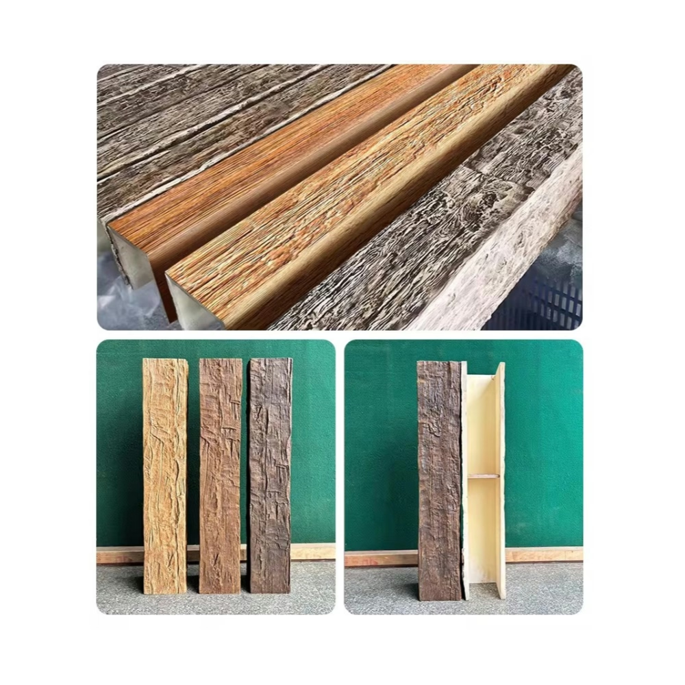
Achieving Continuous Appearance
Texture continuity across splices requires careful orientation of beam sections during assembly. The grain pattern should flow continuously across the splice rather than creating a visible interruption. Achieving this continuity may require rotating beam sections during dry fitting to align grain patterns appropriately.
Color matching between beam sections affects appearance significantly. Beams from the same production batch typically match closely, while beams from different batches may show visible differences. Ordering all beams for a single installation from the same batch ensures the best possible matching.
The finishing process should address splices as early as possible, allowing touch-up work before surrounding elements complicate access. Multiple thin coats of finish blend splice areas with surrounding surfaces, creating the continuous appearance that distinguishes professional work.
Quality Assurance
Inspection during installation verifies that each splice achieves acceptable quality before proceeding. Visual inspection under various lighting conditions identifies any issues that directional lighting might conceal. Physical inspection verifies secure attachment and absence of movement at splice locations.
Load testing provides additional verification for critical applications. Applying test loads that simulate expected service conditions confirms that the installation performs as designed. Any deflection or movement indicates problems requiring correction before the installation is accepted.
Documentation of splice locations, adhesive products, and installation techniques provides valuable reference for future maintenance or modification. This documentation should include photographs showing the installed condition before surrounding work obscures access.
Maintenance Considerations
Long-span beam installations should be inspected periodically for any signs of movement or deterioration. Any observable deflection or change in appearance indicates problems requiring investigation. Early intervention prevents minor issues from progressing to significant repairs.
Support structure conditions should be monitored as part of overall building maintenance. Changes in support conditions affect beam performance directly, potentially creating stresses that splices cannot accommodate. Maintaining support structures protects the beams they carry.
Cleaning and maintenance protocols should be established based on the specific finish and exposure conditions. Following manufacturer recommendations ensures that maintenance activities preserve rather than damage beam appearance.
Technical References
ASTM standards cited in every specification
Test Data
Lab results from internal testing program
Updated 2026
Reviewed against current product specs


