The gap between design vision and installation reality often widens when architectural elements lack comprehensive documentation. Polyurethane faux timber beams, despite their manufacturing precision, can deviate significantly from intended outcomes when installation proceeds without proper technical guidance. Precision technical drawings bridge this gap, translating design intent into actionable instructions that fabricators, contractors, and installers follow consistently. Understanding how these drawings function and what they should contain transforms beam projects from uncertain endeavors into predictable successes.
Professional technical drawings for beam installations extend far beyond simple dimension callouts. They establish coordinate systems that position beams precisely within building spaces, specify connection details that ensure structural integrity, and document finish requirements that achieve design aesthetics. The comprehensive nature of quality documentation prevents the interpretation errors and communication breakdowns that generate costly revisions and schedule delays.
Drawing Set Organization and Standards
A complete beam installation drawing set typically comprises multiple drawing types, each serving specific documentation purposes. Plan drawings provide overhead views showing beam positions relative to room boundaries and other architectural features. These plans establish dimensional relationships and spacing that guide rough framing and coordinate beam installation with other building systems. Elevations complement plans by showing beams as they appear from viewing positions, documenting how exposed surfaces integrate with walls and other vertical elements.
Section drawings reveal internal construction details invisible in plan and elevation views. Cross-sections through beam junctions show how multiple elements connect and how beams mount to building structure. These details translate directly into installation procedures, guiding contractors through complex assembly sequences. Detail drawings zoom into specific connection points, providing the close-up information necessary for accurate fabrication and fastening.
Drawing conventions follow established standards that ensure consistency across drawing sets and enable rapid interpretation by construction professionals. Line weights distinguish between primary dimensional information, secondary detail, and reference content. Dimensioning standards establish how measurements appear and what tolerances apply. Layer organization in computer-generated drawings facilitates selective viewing and automated quantity extraction. Understanding these conventions helps project stakeholders extract accurate information while preventing misinterpretation of critical specifications.
Dimensioning and Tolerance Specifications
Beam installation dimensions require careful specification to balance precision requirements against practical construction tolerances. Overall beam lengths should indicate exact finished dimensions, allowing precise fabrication or selection from available stock. Spacing dimensions between parallel beams need tolerance allowances that accommodate accumulated variations across long runs. Critical dimensions controlling visible alignment typically receive tighter tolerances than internal structural dimensions that don't affect appearance.
Height and elevation specifications require particular attention in beam installations where ceiling relationships create visual impacts. Reference datum points established early in design should carry through all drawings consistently, allowing field verification that installed beams achieve intended ceiling relationships. Vertical positioning may need adjustment based on beam depth variations, requiring coordination between structural and finish dimensions on different drawing sheets.
Tolerance specification requires balancing perfectionism against practical achievability. Exceedingly tight tolerances increase fabrication and installation costs while providing negligible aesthetic benefit for most applications. Professional specifications typically establish tolerances appropriate to visible quality standards, allowing achievable construction without accepting sloppy work. Drawings should clearly indicate which dimensions require tight control and which permit reasonable variation without compromising design intent.
Connection Detail Documentation
Beam-to-structure connections demand the most detailed documentation in beam installation drawing sets. These junctions determine both visual alignment and structural performance, making connection details critical to project success. Quality drawings specify not only hardware types and sizes but also installation sequences that ensure proper load transfer. The complexity of connection details often requires multiple views from different angles, ensuring installers understand how components interact in three-dimensional space.
Beam-to-beam junction details require equal attention when installations include intersecting or spliced beams. The documentation should show how junction surfaces meet, what fasteners or adhesives secure connections, and how finish treatments address junction visibility. Complex intersections involving multiple beams meeting at single points need exploded-view details showing each component's position and orientation before final assembly.
Adjustable connection hardware increasingly appears in beam installations, allowing field compensation for construction variations and alignment adjustment after initial mounting. Technical drawings for these installations must specify adjustment ranges, adjustment hardware location, and final locked-position requirements. Without this information, installers might make inappropriate adjustments or leave hardware unsecured, creating potential performance or safety issues.
Finish and Appearance Documentation
Finish specifications translate design aesthetics into reproducible production requirements. Colors should reference established standards like RAL or NCS rather than subjective descriptions like "warm oak" that different people interpret differently. When custom color matching is necessary, drawings should reference physical samples lodged with appropriate project stakeholders, ensuring consistency between specification and execution.
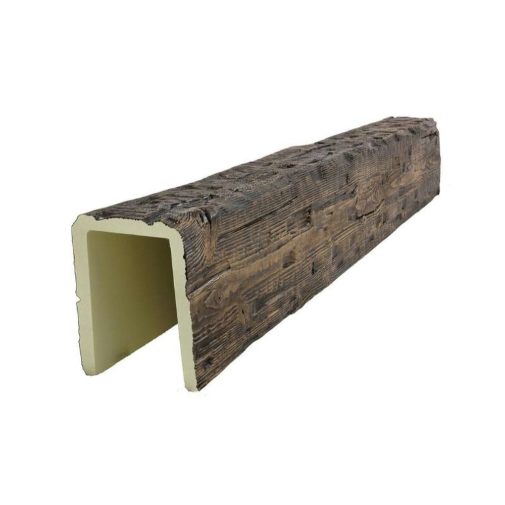
Surface texture requirements deserve documentation that goes beyond generic descriptions. Different manufacturing methods produce different texture characters, and finish treatments modify surfaces further. Drawings should specify texture standards through physical samples, reference photographs, or detailed process descriptions that produce intended results reliably. This documentation prevents the dissatisfaction that arises when aesthetic expectations don't match actual beam appearance.
Grain pattern orientation influences how beams read visually, especially in applications where light catches grain highlights. Drawings may specify grain direction relative to viewing positions or room orientation, ensuring that beams create intended lighting effects. Some installations benefit from consistent grain orientation across multiple beams, while others intentionally vary orientation to create visual interest. Either approach requires documentation that communicates the intended treatment.
Coordination with Other Building Systems
Beam installations intersect with numerous other building systems requiring coordination documentation. Electrical routing through beam cavities needs documentation showing wire paths, junction box locations, and access provisions for maintenance. HVAC distribution may penetrate beams or require clearance zones around beam installations. Structural engineering for floor or roof loads above beams requires coordination that ensures beam mounting can resist anticipated loads.
Ceiling system coordination deserves particular attention in projects combining beams with other ceiling treatments. Soffit constructions, recessed lighting, and decorative plasterwork all interact with beam installations, requiring dimensional coordination that drawings should establish clearly. Interface details showing how different ceiling elements meet and transition ensure that different trades execute coordinated work rather than conflicting installations.
Acoustic and thermal performance requirements may influence beam specification and installation procedures. Drawings should document any insulation requirements within beam cavities, acoustic mounting isolation from structure, and thermal break provisions where thermal bridging might occur. These technical requirements often appear in specifications rather than drawings, but coordination between drawing documentation and specification text ensures consistent information delivery to installation teams.


The investment in comprehensive technical documentation pays dividends throughout the project lifecycle. Construction teams receive clear guidance that reduces uncertainty and supports efficient installation. Designers can verify that completed work matches intended design without ambiguity. Building owners receive documentation valuable for future maintenance and renovation. By treating technical drawings as essential project infrastructure rather than optional deliverables, stakeholders transform beam installations from artistic aspirations into built reality matching design vision.
Technical References
ASTM standards cited in every specification
Test Data
Lab results from internal testing program
Updated 2026
Reviewed against current product specs


