Modern architectural practice relies heavily on computer-aided design tools, from initial concept modeling through construction documentation. Polyurethane faux beams that integrate seamlessly with these workflows streamline design processes and reduce coordination errors. Understanding how beam specifications translate into digital formats helps architects and designers work more efficiently.

Digital Format Options
DXF and DWG formats provide broad compatibility across CAD platforms. These formats preserve geometric information that represents beam profiles accurately. Profile drawings in these formats can be inserted directly into design documents or used to generate 3D models. Most beam suppliers can provide profile drawings in these standard formats upon request.
Revit family files enable direct integration with Building Information Modeling workflows. Family files define beam geometry, materials, and parametric relationships that support design development and documentation. BIM families can be scheduled, tagged, and coordinated with other building elements using standard Revit tools.
SketchUp components offer similar functionality for designers working in that platform. Component libraries allow drag-and-drop placement of beam elements within 3D models. SketchUp's intuitive interface makes these components accessible to designers who may not work extensively in more technical CAD environments.
Rhino and other NURBS-based modeling platforms require different geometry approaches that preserve curved and organic surfaces. Some premium beam profiles include smooth curved elements that benefit from NURBS representation. Suppliers with experience in architectural modeling can provide geometry in appropriate formats.
Profile Library Development
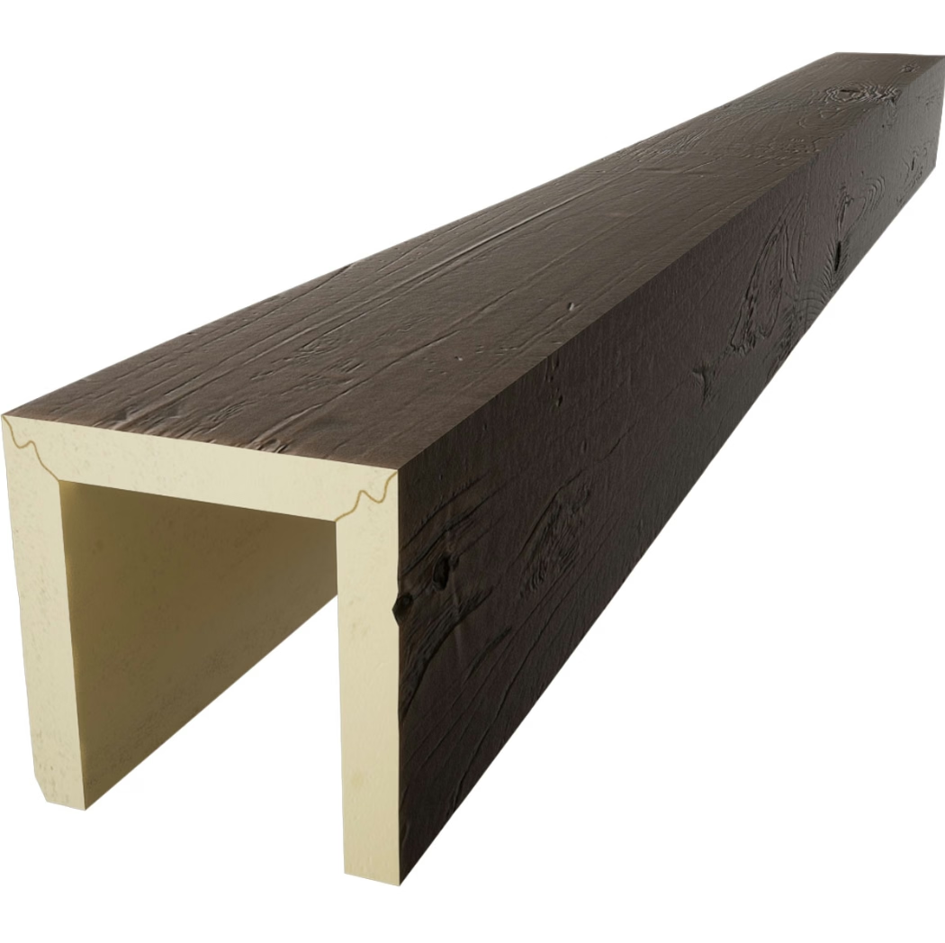
Standard profile libraries include common beam shapes that cover most residential and commercial applications. Rectangular, square, and I-beam profiles represent the most frequently specified options. More elaborate profiles like timber frame reproductions and decorative corbels may require custom library development.

Profile parameterization allows dimensions to adjust automatically when specifications change. Parametric families respond to length, width, and height changes while maintaining proper proportions. This capability proves valuable when beam sizes are determined by structural requirements or aesthetic refinement.
Material assignment within CAD files enables accurate visualization and quantity reporting. Defining materials correctly allows BIM tools to calculate material quantities and costs. Material properties like weight affect structural calculations in some modeling approaches.
Annotation standards ensure that beam schedules and callouts communicate effectively across project teams. Standardized annotation approaches reduce confusion and prevent errors that arise from inconsistent terminology. Reference standards like CSI MasterFormat help organize specifications consistently.
3D Modeling Best Practices
Level-of-development planning determines how much detail to include at each design phase. Early phases benefit from simplified representations that communicate intent without excessive detail. Detailed modeling with accurate profiles occurs later when design is more established and changes are less likely.
Model hierarchy organizes beam families within larger building models. Proper nesting allows beams to be selected individually or in groups for editing and documentation. Consistent organization practices across project teams facilitate coordination and reduce time spent locating elements.
Coordination with structural and mechanical systems ensures that beams fit within overall building design. BIM collision detection identifies conflicts where beams interfere with ducts, pipes, or structural elements. Running coordination checks throughout design development catches problems early when correction costs less.
Detail levels for construction documents may exceed what's appropriate for design development. Transitioning from design models to construction-ready documentation requires adding details that may not exist in simplified design families. Planning for this transition prevents documentation delays.
Quantity Takeoff and Scheduling
Automated quantity extraction from BIM models provides more accurate material estimates than manual measurement. Properly constructed beam families generate accurate linear measurements when scheduled. Multiple beam types can be quantified simultaneously, enabling rapid cost estimation.
Material type differentiation allows separate quantities for different beam specifications. Projects using multiple beam finishes or profiles benefit from schedules that break out each type separately. This differentiation supports procurement and cost tracking throughout projects.
Waste factor application accounts for cutting and fitting losses during installation. Standard waste percentages vary by project type and installation complexity. Applying appropriate factors to extracted quantities prevents under-ordering that would require expensive follow-up purchases.
Cost loading in BIM enables value estimation before detailed specification is complete. Unit costs assigned to beam families generate preliminary budgets that guide design decisions. As specifications become more detailed, costs can be refined for more accurate budgeting.
Specification Integration
Drawing notes should reference beam specifications clearly for contractor reference. Notes that specify manufacturer, product line, finish, and installation requirements prevent substitution and establish quality expectations. Standard drawing note formats help contractors locate relevant information quickly.
Specification writing should coordinate with drawing representation to ensure consistency. Changes to either drawings or specifications require corresponding updates elsewhere. Coordination procedures that identify when updates are needed help maintain consistency throughout documentation development.
Shop drawing submittal requirements should be defined in project specifications. Requesting approved samples, CAD files, and installation drawings establishes expectations for contractor deliverables. Review procedures should allow adequate time for submittal review before construction requires beams.
Collaborative Workflows
Cloud-based design platforms enable real-time collaboration on beam layouts and specifications. Multiple team members can work simultaneously on beam design, reducing iteration time. Version control features track changes and support rollback if corrections become necessary.
Issue tracking during design development identifies beam-related problems for resolution. When coordination checks reveal conflicts or specifications prove problematic, tracking issues ensures they receive attention. Closing resolved issues prevents them from being forgotten or revisited unnecessarily.
Rendered visualization using CAD models helps clients understand beam installations before commitment. Photorealistic rendering from 3D models shows how beams will appear in completed spaces. These visualizations support design decisions and client approval processes.
Handoff documentation transfers design intent to construction teams effectively. PDF drawings, 3D models, and specification documents together communicate complete requirements. Package contents should be clearly organized so contractors can find relevant information efficiently.
Technical References
ASTM standards cited in every specification
Test Data
Lab results from internal testing program
Updated 2026
Reviewed against current product specs


