
The difference between an amateur beam installation and a professional one often comes down to what happens before any beam touches the ceiling. Careful measurement and meticulous marking create the framework that guides every subsequent action, turning abstract design intentions into physical reality. Installers who rush through this preparatory phase inevitably spend more time correcting errors than they saved by skipping the careful work.
Measurement and marking serve multiple purposes simultaneously. They define the exact position of every beam, establish reference points for cutting and fitting, and provide verification standards against which completed work can be judged. Neglecting any of these functions compromises the installation quality, even if the others receive full attention.
Foundation Measurement Principles
Begin every project with a comprehensive survey of the existing conditions. Measure the room's actual dimensions at multiple points rather than relying on plans or previous measurements. Plans contain approximations, and walls shift over time, so the existing conditions always take precedence. Record all measurements systematically, noting which walls were measured and where, to prevent confusion when coordinating multiple dimensions.
Measure horizontally across the ceiling at the planned beam locations to establish the span each beam must cover. In an ideal world, opposite walls would be exactly parallel, but older buildings particularly may show significant variation. When spans vary across the ceiling, decide whether to plane beam ends to match varying wall positions or to maintain consistent beam length and address gaps with finishing techniques. This decision affects both material requirements and the installation approach.
Measure vertically from floor to ceiling at multiple points when beam height placement matters. Spaces with cathedral ceilings or multiple levels require height verification across the entire installation area. Variations in ceiling height affect how beams appear when viewed from different positions and may require adjustment to maintain visual consistency.
Transfer critical measurements to a dimensioned sketch that serves as the installation reference document. This sketch should show all room dimensions, beam positions, blocking locations, and any architectural features that influence the installation. Professional installers keep this sketch accessible throughout the project and update it when conditions change or adjustments become necessary.
Tool Selection and Calibration

The quality of your measuring tools directly affects installation accuracy. Invest in a premium tape measure with a blade that remains straight when extended and a hook that moves appropriately for inside and outside measurements. Cheap tapes accumulate errors that compound across multiple measurements, eventually creating significant placement problems.
Digital laser distance meters eliminate cumulative measurement error by measuring directly from point to point rather than adding sequential measurements. For rooms with complex geometries or long spans, these tools provide accuracy impossible to achieve with tape measures. They also make one-person measurement feasible where two people would otherwise be required for tape-based measurements.
Verify tool accuracy before beginning critical measurements. Check tape measures against a known standard and note any deviation. Calibrate laser levels against established benchmarks, particularly after transport or rough handling. Small calibration errors become large positioning mistakes over distance, so regular verification prevents cumulative error from affecting the installation.
Maintain marking tools in good condition. Replace pencils before they become dull and produce inconsistent lines. Keep marking pens capped to prevent dry-out, and test marking visibility from below before committing to a marking approach. Inconsistent marking leads to inconsistent results, so standardize your marking tools and techniques across the entire project.

Layout Line Creation and Transfer
Create definitive layout lines that guide actual beam placement rather than approximate guides. A line represents an exact position, while a mark or dot allows interpretation that may vary across the installation. When accuracy matters, draw full lines rather than relying on points that must be connected mentally during installation.
Use a chalk line for creating long straight lines across ceilings and walls. This tool snaps crisp reference lines that remain visible throughout the installation process. Choose chalk colors that contrast with the background surface and resist accidental smearing. Blue chalk works well on most surfaces and cleans up relatively easily after the installation completes.
For curved or irregular layouts, create templates that capture the actual geometry of the situation. Cardboard or thin plywood templates allow trial fitting before committing to beam modification. Mark templates clearly with orientation and reference information to prevent confusion during the actual installation.
Transfer layout information between surfaces systematically. Ceiling layouts must connect to wall reference points, and beam positions must align across multiple attachment points. Develop a consistent method for transferring measurements and positions that can be repeated reliably across all beams. Check transferred points for consistency before proceeding with beam installation.
Blocking and Support Marking
Accurate blocking placement requires marking that identifies both position and extent. Mark the center point of each blocking piece and draw lines indicating the width of the blocking material. This prevents confusion about where blocking ends and empty space begins, which matters significantly when driving fasteners through the beam into blocking.
Indicate blocking height relative to the planned beam height, not relative to the ceiling surface. The blocking must be set to a precise elevation that allows the beam to sit at the correct height when attached. Measure from your established reference plane rather than from the potentially uneven ceiling surface.
Group blocking marks logically so that installation proceeds efficiently. Sort blocking by position, height, and type to minimize adjustment during the actual installation. Mark blocking for all beams in an area before beginning installation, rather than marking and immediately installing each beam individually. This batch approach improves efficiency and reduces the chance of missing critical blocking.
Verify blocking alignment with a long straightedge before marking attachment points. Blocking that looks level when checked individually may create a stepped pattern when multiple pieces are positioned. Use your reference layout lines to confirm that all blocking in a continuous run maintains consistent positioning.
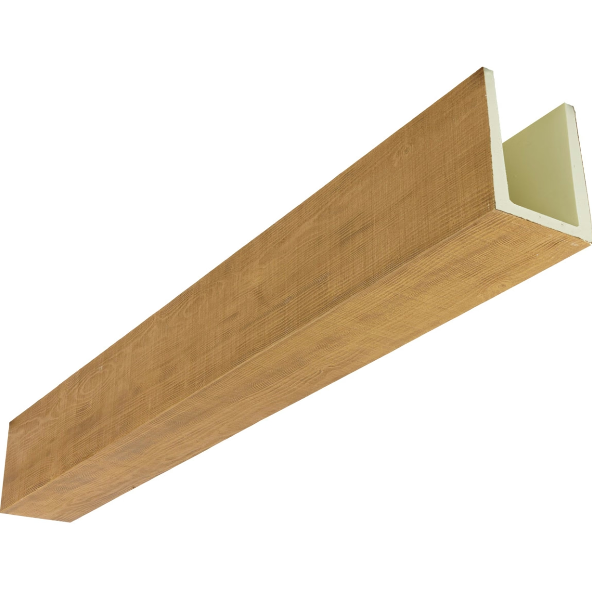
Verification Checklists Before Cutting
Develop a systematic verification process that confirms layout accuracy before any beam modification begins. Check all critical dimensions one final time, rotating responsibility between team members if multiple people participated in the original measurement. Fresh eyes catch errors that familiar eyes overlook.
Verify that all beams scheduled for installation are present and undamaged before marking. Discovering a missing beam or significant damage after cutting other beams creates efficiency problems and potentially wastes material. Confirm beam quantities and condition before committing to any irreversible process.
Test fit beams in position before making any cuts. Even brief positioning reveals issues that measurement alone might miss, such as beams that don't nest properly with adjacent pieces or surfaces that interfere with planned beam positions. Dry fitting also confirms that blocking positions align with beam mounting hardware.
Document your verification process with photographs that show layout lines, blocking positions, and any significant conditions encountered. This documentation proves valuable if questions arise later about why certain decisions were made or where specific blocking is located behind installed beams.
Technical References
ASTM standards cited in every specification
Test Data
Lab results from internal testing program
Updated 2026
Reviewed against current product specs


