
The invisible work of mounting brackets determines whether beams stay put or eventually sag, shift, or fall. Every bracket carries a portion of the beam weight and transfers that load to the structural ceiling, distributing forces appropriately to prevent localized stress. Calculating proper bracket spacing requires understanding load dynamics, material characteristics, and the specific requirements of your beam profile.
Spacing decisions affect both immediate installation quality and long-term performance. Tight bracket spacing provides redundancy and stiffness, but increases installation time and material cost. Wider spacing reduces cost and complexity but demands more precision in each attachment point. The professional approach balances these considerations against the specific requirements of each installation.
Understanding Load Dynamics
Beam weight creates the primary load that brackets must support. PU faux beams are significantly lighter than solid timber, which reduces the total load but also means the material provides less inherent stiffness. A heavy timber beam resists sagging through its own mass, while a lightweight PU beam depends more heavily on bracket support to maintain position. This distinction matters for spacing calculations.
Span length dramatically affects the load distribution across brackets. A short beam spanning between two brackets carries relatively uniform load with each bracket supporting roughly half the total weight. A long beam spanning multiple brackets experiences different load dynamics, with brackets at the ends supporting more load than those in the middle due to beam stiffness effects. Calculate loads based on actual span conditions rather than simple division.
Dynamic loads from building movement, thermal expansion, and occasional contact add stress beyond static weight. Beams in high-traffic areas, locations with significant temperature variation, or spaces with structural settling experience additional forces that bracket spacing should accommodate. Factor in appropriate safety margins based on the specific conditions of each installation.
Ceiling structure type influences bracket load capacity. Wood joists provide excellent fastener withdrawal resistance and distribute loads across multiple framing members. Steel structures may require different attachment approaches with specialized hardware. Masonry and concrete surfaces demand anchor systems with specific load ratings. Always verify that your planned attachment point can actually support the loads you will apply.
Calculating Optimal Bracket Spacing

Start bracket spacing calculations with basic information: beam length, beam weight per linear foot, bracket load capacity, and ceiling structure characteristics. With these inputs, determine the maximum spacing that maintains acceptable load per bracket. Professional installers typically work toward forty to fifty percent capacity utilization, providing margin for unexpected loads and building movement.
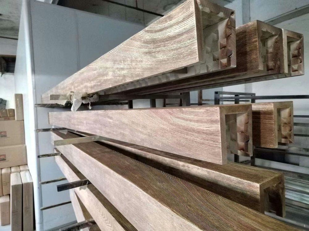
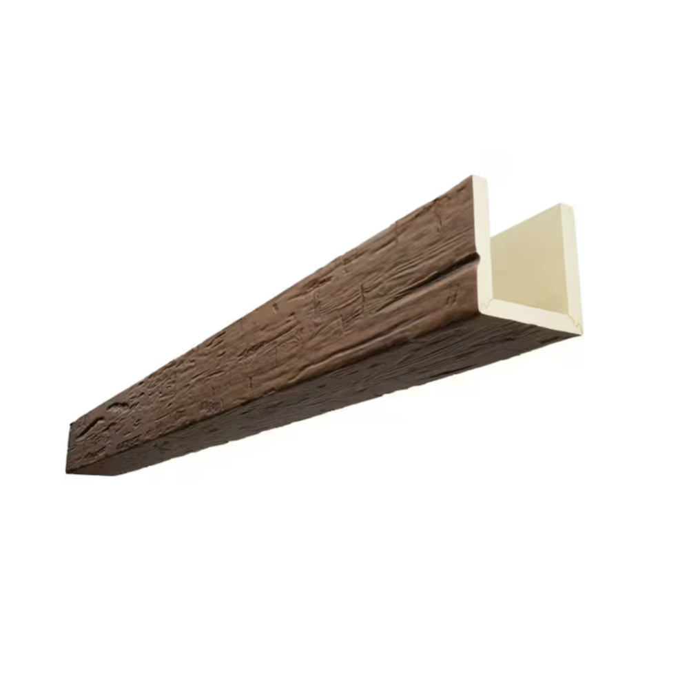
Consider beam profile rigidity when calculating span limits. Box-style beams with flat bottoms resist sagging differently than beams with curved profiles or complex cross-sections. Stiffer beam profiles can span greater distances between brackets without visible deflection, while flexible profiles require tighter spacing to maintain appearance. Manufacturer specifications often include recommended maximum spans based on standard load assumptions.
Account for bracket position along the beam when determining spacing. End brackets experience different load conditions than middle brackets and sometimes require closer spacing or additional reinforcement. Corners and intersections create stress concentrations that benefit from reduced spacing at those locations. Position brackets to address these variations rather than applying uniform spacing throughout.
When beam lengths create non-standard spans, adjust bracket spacing to match the available structure rather than forcing structure to match standard spacing. Blocking can be added between joists to create attachment points at calculated positions. Some installations benefit from custom blocking layouts designed specifically for the beam spacing requirements.
Hardware Selection and Capacity
Select brackets rated for the loads your installation requires, with appropriate safety margins. Manufacturer-provided load ratings assume ideal conditions, so professional installers apply reduction factors based on actual conditions. Factors like fastener quality, structure condition, and access for proper installation all affect the effective capacity you should design toward.
Bracket material matters for long-term performance. Steel brackets provide high strength but require protection against corrosion in humid environments. Stainless steel offers excellent corrosion resistance for challenging conditions but at higher cost. Aluminum brackets work well for lighter beams and resist corrosion naturally but may not provide sufficient strength for heavy applications.
Consider concealed versus exposed bracket systems for aesthetic impact. Concealed brackets create clean appearances but offer less adjustment after installation. Exposed brackets may provide more robust attachment but interrupt the beam appearance. Match bracket selection to the priority between visual appearance and attachment security for each project.
Specialty brackets address specific installation challenges like angled ceilings, beams crossing obstructions, or beams requiring unusual support configurations. Inventory specialty brackets for common situations, and establish ordering relationships for unusual requirements. Some installations require custom bracket fabrication to address unique conditions.
Installation Techniques for Secure Attachment
Position brackets precisely according to your spacing calculations, using reference marks established during the layout phase. Small position errors accumulate across the beam length, eventually creating visible misalignment at the beam ends. Double-check bracket positions before driving any fasteners, as bracket repositioning after initial fastening damages both the bracket and the structure.
Fasten brackets using appropriate hardware for each attachment surface. Wood framing accepts screws sized for the bracket holes with sufficient length to penetrate well into the joist. Steel framing requires self-drilling screws or bolts with locking washers. Masonry and concrete demand anchors selected for the specific substrate and load requirements.
Tighten fasteners to manufacturer specifications without over-tightening. Stripped fastener heads or bent brackets result from excessive force that serves no useful purpose. Use calibrated torque wrenches for critical applications, and verify a representative sample of fasteners with a hand torque meter to confirm proper tightening.
Support beams temporarily during bracket installation to prevent stressing the brackets before they are fully secured. A helper or temporary support keeps the beam in position while brackets are attached. Premature beam weight on partially installed brackets creates stress concentrations that weaken the connection.
Verification and Quality Assurance
After bracket installation but before beam mounting, verify that all brackets are properly positioned, securely attached, and aligned with each other. A straightedge across bracket tops reveals any height variations that would create beam alignment problems. Check bracket angle consistency for beams requiring non-vertical mounting.
Test bracket attachment by applying moderate downward force to verify the connection holds. This load test should not approach the rated capacity but should confirm that fasteners are properly engaged and the structure is responding as expected. Brackets that shift or feel loose under test load require investigation and correction before proceeding.
Document bracket positions for future reference, particularly blocking locations hidden behind beams. This documentation helps with future maintenance, renovation planning, or troubleshooting if problems develop. Create a simple diagram showing bracket positions relative to room features that remain visible after installation.
Perform final verification after beam installation to confirm that brackets are performing as expected. Check for any movement or noise when beams are loaded, and address any issues immediately. Early detection of problems prevents more serious issues from developing and allows correction while the repair options remain simple.
Technical References
ASTM standards cited in every specification
Test Data
Lab results from internal testing program
Updated 2026
Reviewed against current product specs


