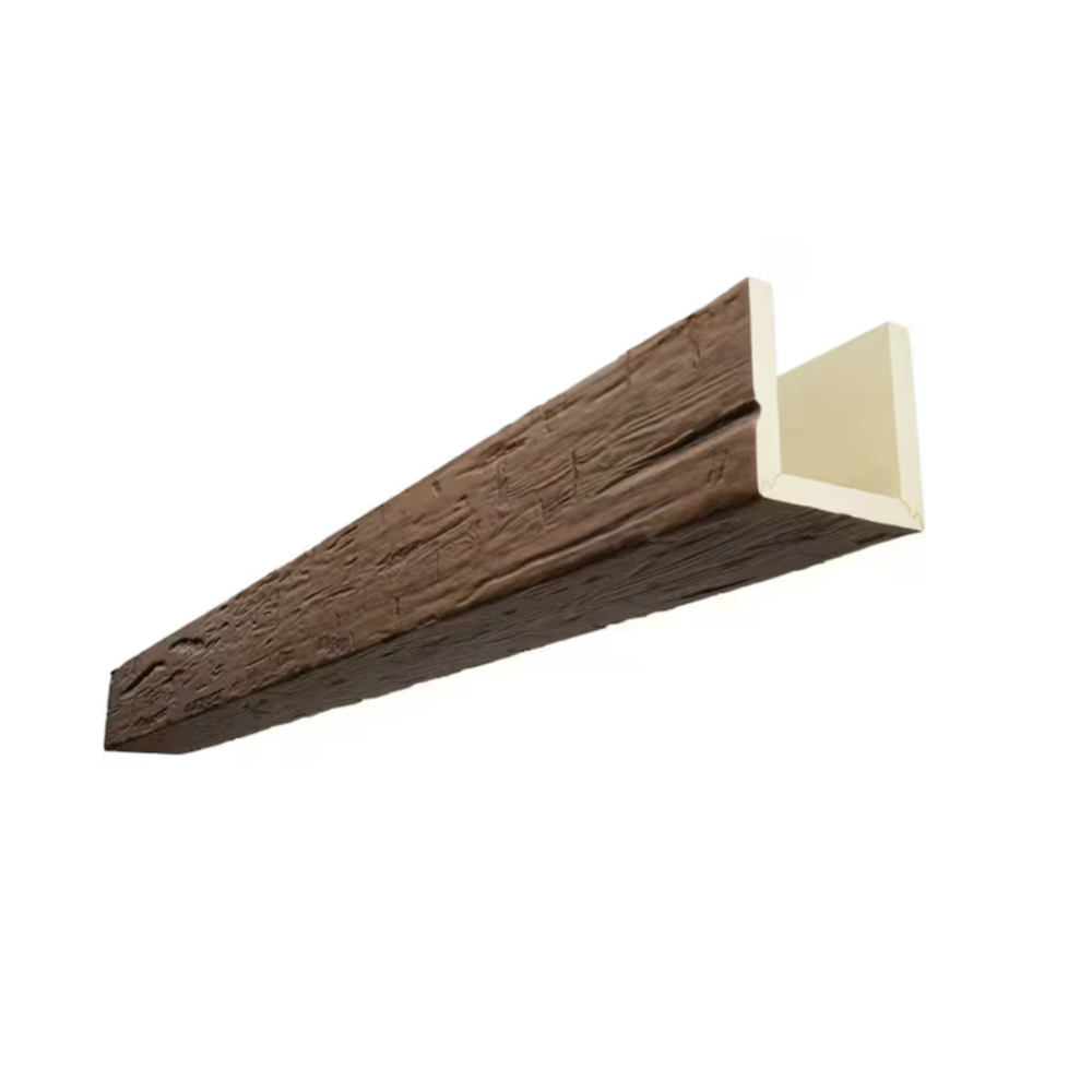
Ceiling beam installations succeed or fail based not on how they appear from directly below but on how they register from the positions where people actually spend time in the room. Professional designers understand this fundamental principle, evaluating sight lines from seating areas, primary traffic routes, and work zones before finalizing beam layouts. What appears perfect when viewed head-on from the room's center may reveal awkward joints, misaligned spacing, or poor termination points from practical viewing angles.
Sight line assessment transforms ceiling design from abstract geometric exercise into user-centered experience planning, ensuring that installation investments deliver visual returns proportionate to their cost. This evaluation process requires both analytical technique and developed aesthetic judgment, skills that distinguish professional installations from amateur attempts that may score well on paper but disappoint in actual use.
Understanding Human Perception in Elevated Spaces
Human visual perception evolved to prioritize information at eye level and below, treating overhead elements as peripheral environmental context rather than focal points. This perceptual hierarchy means that ceiling beams rarely receive the focused attention that wall-mounted elements command, but when they do attract notice, imperfections become jarring precisely because they exist outside expected viewing patterns. Professional installers exploit this relationship by ensuring that beam features most likely to receive attention present their best faces while accepting minor compromises in areas rarely scrutinized.
Entry points and primary seating locations establish viewing baselines that anchor subsequent analysis, with sight lines from these positions forming the evaluation framework for beam placement decisions. Multiple viewing positions require consideration when rooms host varied activities, as living rooms with multiple seating groups, restaurants with distributed table arrangements, or open-plan offices with varied workstation orientations each present distinct perspective requirements.
Analytical Sight Line Mapping
Professional designers employ systematic mapping techniques that translate subjective impression into quantifiable planning data, beginning with floor plans marked to identify primary viewing positions, traffic flows, and furniture placement. From each identified position, analysts sketch lines extending to the ceiling plane at typical viewing angles—typically 30 to 45 degrees from horizontal for seated observers and 15 to 25 degrees for standing viewers—establishing which ceiling areas receive direct sight line exposure.

These sight line maps reveal which beam sections fall within primary viewing zones and which remain peripheral, enabling differentiated attention during installation. Primary zone beams warrant premium positioning attention with joints placed for minimal visibility, while peripheral beams accept compromises that would prove unacceptable in focal areas. The resulting hierarchy guides subsequent layout decisions without requiring every beam to meet the same exacting standard.
Impact of Room Geometry on Beam Layout
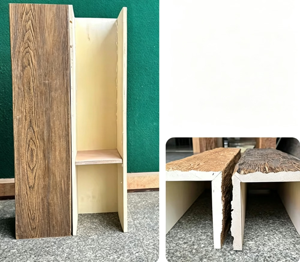
Room shape fundamentally constrains viable beam layouts, with rectangular spaces supporting regular grid patterns while irregular polygons or curved boundaries demand custom solutions that may sacrifice some design purity for practical feasibility. Long narrow rooms often benefit from beams running across the shorter dimension, which visually widens the space while fitting longer beams without excessive cutting. Square rooms accommodate either direction with equal facility, potentially rotating patterns to align with architectural features or furniture arrangements.
Sloped ceilings, cathedral volumes, and multi-level configurations introduce additional complexity by creating zones with different viewing characteristics. Upper wall areas where ceiling slopes begin may hide beam ends naturally, eliminating awkward termination concerns in those zones. High ceilings reduce visible detail as beams recede into the distance, potentially justifying simpler installation methods that would prove unacceptable at lower heights.
Natural Light Interaction with Beams
Daylight patterns shift throughout the day and seasons, potentially illuminating beams from dramatically different angles and intensities at different times. North-facing rooms maintain relatively consistent natural lighting with soft, even illumination, while south-facing spaces experience pronounced directional light that creates strong shadows accentuating beam depth and texture. Professional assessment considers how expected lighting conditions interact with beam design, adjusting texture depth, finish selection, and even orientation to optimize performance under likely conditions.
Artificial lighting introduces additional considerations including fixture placement, lamp color temperature, and switching arrangements that might illuminate spaces differently depending on activity patterns. Downlights positioned between beams create pools of light that dramatize individual beam surfaces while casting pronounced shadows across texture. Coffered effects achieved by uplighting beam undersides produce entirely different impressions, potentially making beam depth the dominant aesthetic characteristic rather than surface appearance.
Practical Application in Installation Planning
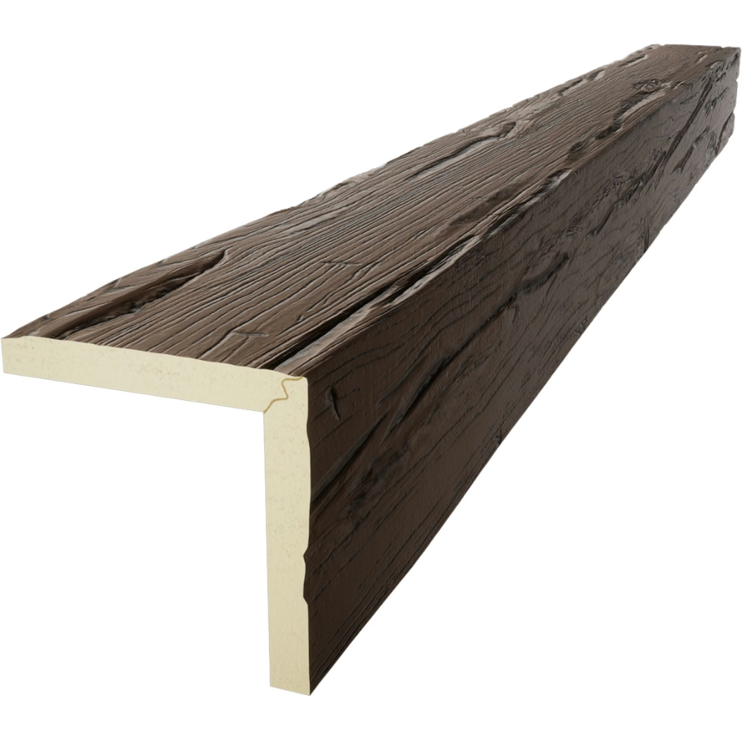
Translating sight line analysis into installation practice requires translating abstract zones into concrete beam positions, spacing calculations, and termination details. Marking reference lines on the ceiling surface at actual installation height verifies that planned positions align with expected viewing positions, enabling adjustments before commitment. Mock-up installation of representative beam sections provides final validation opportunity before completing full installation.
Documentation of sight line considerations enables productive conversations with clients about design rationale, helping them understand why certain decisions were made rather than alternatives they might have preferred. This explanation capability distinguishes professional practice from simple product installation, building client confidence and reducing second-guessing after installation completion.
Technical References
ASTM standards cited in every specification
Test Data
Lab results from internal testing program
Updated 2026
Reviewed against current product specs