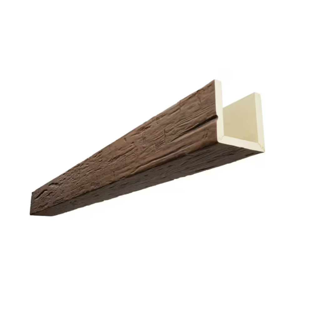
Beam spacing fundamentally shapes how ceiling installations read spatially, with spacing decisions determining whether results feel spacious or cramped, formal or casual, authentic or theatrical. Unlike structural timber where spacing follows engineering requirements, faux beam installations free designers to pursue aesthetic objectives, but this freedom creates decision challenges that require thoughtful approach to produce satisfying results. Professional spacing design balances mathematical precision with visual judgment developed through extensive practice across diverse project types.
Understanding why certain spacing relationships feel inherently correct helps designers move beyond arbitrary rules toward principled decision-making that adapts appropriately to each project's unique requirements. The goal is not rigid adherence to formulas but informed judgment that produces satisfying results across the wide variety of spaces and applications these installations address.
Proportion Principles Based on Room Scale
Ceiling height establishes the primary scaling reference for beam proportion decisions, with taller ceilings accommodating larger beams and wider spacing while lower ceilings require more modest dimensions to avoid overwhelming the space. A beam depth equaling approximately 1/15 to 1/20 of ceiling height creates balanced proportions in typical residential applications, though this guideline adjusts based on desired visual weight and architectural context.
Room volume matters as much as height alone, with large open spaces supporting bolder statements than intimate rooms where subtle treatment proves more appropriate. Grand foyers, great rooms, and hospitality venues can carry substantial beams with generous spacing that would prove oppressive in cozy dining rooms or intimate bedrooms. Assessing the experiential character of spaces—not merely their dimensions—guides proportion selection that serves rather than dominates the architecture.

Window and door proportions interact with ceiling treatment, with tall windows or expansive glass areas creating visual connections that beam spacing should complement rather than compete against. Highly transparent facades often benefit from restrained beam treatment that emphasizes openness rather than adding visual mass that contradicts the architecture's intent. Conversely, heavily ornamented historic interiors might welcome bold beams that reinforce architectural character.
Grid Patterns and Their Visual Effects
Regular grid spacing creates formal, ordered appearances appropriate for contemporary spaces and traditional interiors seeking classical balance. Equal spacing between all beams establishes rhythm and predictability that many clients find reassuring, particularly in commercial applications where brand consistency matters. Grid layouts also simplify installation by eliminating special-case calculations for irregular intervals.
Symmetrical spacing centered on room features produces formal arrangements that align beams with focal points and architectural elements. Entry points, fireplace surrounds, and primary seating arrangements all provide reference anchors for symmetric layout development. This approach proves particularly effective in traditional architecture where balance and formality align with established design language.
Asymmetric spacing can produce dynamic, contemporary results when executed with intention, breaking regular patterns to create visual interest through variation. This approach requires confident design judgment, as arbitrary asymmetry reads as error rather than intentional design choice. Successful asymmetric layouts typically maintain overall balance despite individual variations, creating resolved compositions rather than random-looking arrangements.

Spacing for Different Beam Configurations
Single beams installed along ceiling planes create minimal visual interruption, with spacing concerns limited to distance from walls and relationship with other ceiling elements. These installations benefit from spacing that maintains consistent margins from walls, with the beam position reinforcing rather than contradicting architectural symmetry.
Paired beam configurations—where two beams run parallel with minimal separation—create apparent structural members while maintaining relatively light visual impact. Spacing between beam pairs typically ranges from two to four times the individual beam spacing, creating groupings that read as unified elements while maintaining individual member definition. This approach suits spaces where substantial ceiling coverage is desired without the visual density of continuous parallel beams.
Coffered ceiling layouts integrate beams with recessed panels, creating classic architectural detailing that requires precise spacing calculations to achieve proper proportion. Standard coffer proportions typically establish panel depth at approximately 1/5 to 1/3 of the beam depth, with panel width approximately 1.5 to 2 times the panel depth. Following established proportion relationships ensures results that feel architecturally authentic rather than arbitrary.
Practical Spacing Calculations
Converting desired spacing relationships into actual measurements requires reconciling room dimensions with aesthetic objectives, often revealing tensions that require compromise. For example, a room requiring five equal spaces might need 92cm spacing, but this creates beam positions that conflict with light fixture locations. Iterative adjustment toward workable solutions that satisfy practical constraints while maintaining design intent produces better results than rigid adherence to ideal proportions.
Beam run planning accounts for interruptions including ceiling lights, HVAC diffusers, structural elements, and fire sprinkler heads that create obstacles requiring beam notching, fixture relocation, or spacing adjustments. Mapping these constraints against desired spacing patterns reveals conflicts early enough for resolution rather than during installation when options prove limited. Professional installers appreciate detailed obstacle documentation that enables accurate material preparation and installation sequencing.
Edge conditions at walls require attention to detail, with beam termination positions determining whether the installation feels resolved or awkward. Spacing calculations should ensure that end beams maintain consistent relationships with walls across multiple runs, avoiding situations where one wall receives a half-space margin while another receives a full space. When ideal symmetry proves impossible, accepting slight asymmetry in less visible locations preserves apparent order where it matters most.
Documentation and Communication
Professional spacing documentation communicates layout intent clearly enough for accurate execution without constant supervision, including dimension callouts, reference line locations, and special condition details. Elevation drawings showing beam positions from multiple viewing directions enable visualization before commitment, while plan views provide installation reference during execution. Photographic documentation of mock-up installations captures decisions that drawings cannot fully convey.
Client presentation of spacing options enables informed decision-making, with clear explanations of tradeoffs between alternatives helping clients understand design rationale. Some clients prefer mathematical precision that produces regular, predictable patterns, while others appreciate the character that slight variations introduce. Documenting client preferences protects against post-installation dissatisfaction when results reflect stated preferences rather than assumed ones.
Technical References
ASTM standards cited in every specification
Test Data
Lab results from internal testing program
Updated 2026
Reviewed against current product specs