The security of beam installations depends fundamentally on how well fasteners connect beams to their supporting structure. While mounting systems vary, screw fastening remains one of the most common and reliable methods for securing polyurethane beams. Understanding proper screwing techniques ensures that beams remain firmly attached throughout their service life, resisting the forces that can loosen or fail connections over time.
Polyurethane's material characteristics require slightly different approaches than fastening in natural wood or metal. The material is firm enough to hold screws securely but compresses differently than wood, requiring consideration of pilot hole sizing and screw selection. These differences are minor but important for achieving optimal results.

Screw Selection for Polyurethane Substrate
Screw type affects holding power significantly. Coarse-thread screws provide excellent grip in polyurethane by engaging more material per thread, while fine-thread screws work well but may require slightly larger pilot holes. The choice between these options matters less than ensuring threads engage fully without excessive resistance during installation.
Stainless steel screws provide corrosion resistance that protects connections in humid environments or exterior applications. While polyurethane itself does not corrode, moisture can travel along screw shafts to affect the supporting structure or appear as staining on beam surfaces. Coated screws offer an alternative for interior applications where cost considerations favor them over stainless steel.
Screw length should penetrate adequately into the supporting structure while leaving sufficient thread engagement in the beam. A minimum of one inch penetration into structural backing typically provides adequate strength, though specific requirements depend on loads and backing conditions. Calculating total thickness—beam plus any air gap plus support—ensures screws are long enough for the actual conditions.
Pilot Hole Preparation
Pilot holes prevent splitting and ensure clean screw entry that maintains surface appearance. The pilot hole should be slightly smaller than the screw core diameter, allowing threads to engage while providing space for material displacement. A hole equal to the screw's root diameter provides a starting point, with adjustments based on observed results.
Drill bit selection matters for clean, accurate holes. Sharp bits create clean holes without tearing or burning the polyurethane surface. Dull bits may create irregular holes that affect screw alignment and appearance. Inspect bits before use and replace or sharpen those showing significant wear.
Depth of pilot holes should accommodate screw length without bottoming out. When screws bottom against solid material before fully inserted, they cannot develop proper clamping force. Drill pilot holes deep enough that screws can run freely until the head contacts the beam surface.
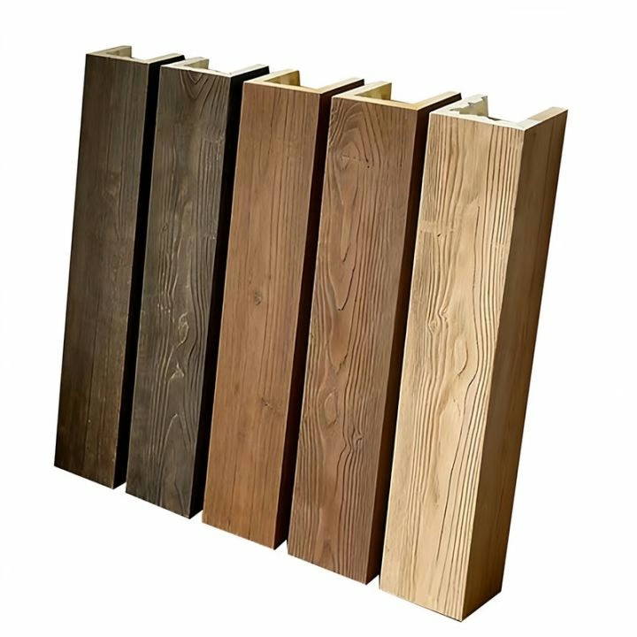
Installation Technique and Spacing

Starting screws perpendicular to the surface prevents wandering that creates crooked insertions and potentially damaged surfaces. Begin with the screw positioned at the desired location and apply firm pressure while starting the threads. Once threads have engaged, reduce pressure and allow the screw to draw itself in.
Power driver speed control affects results significantly. High-speed driving risks stripping threads or cracking the material around the screw head. A lower speed that allows threads to engage steadily provides better results. Some installers prefer to finish tightening with a hand screwdriver, feeling the resistance that indicates proper torque.
Spacing between screws distributes loads appropriately and prevents stress concentrations. Generally, screws should be spaced at intervals of 12 to 24 inches along the beam length, with tighter spacing near joints and corners where loads concentrate. The specific spacing depends on beam size, profile, and anticipated loads, but conservative spacing provides insurance against failure.
Addressing Common Problems
Stripped threads occur when screws are driven too fast, into holes that are too large, or with excessive force. If threads strip during installation, the screw should be removed and the hole filled with a polyurethane-safe filler before reinserting. For critical applications, consider using larger screws or switching to adhesive bonding to restore holding power.
Surface cracking around screw heads results from excessive driving force or pilot holes that are too shallow. Prevention involves proper pilot holes and controlled driving force. If cracking occurs, assess whether the crack affects structural integrity or appearance. Minor surface cracks may be repairable with filler, while extensive cracking may require beam replacement.
Screw head visibility can be addressed through various approaches depending on the finish system. Countersinking allows screw heads to be filled and painted over, creating invisible fastening. Alternatively, decorative caps or covers can be applied over screw heads for a finished appearance. Planning for these details during specification prevents decisions made under time pressure during installation.
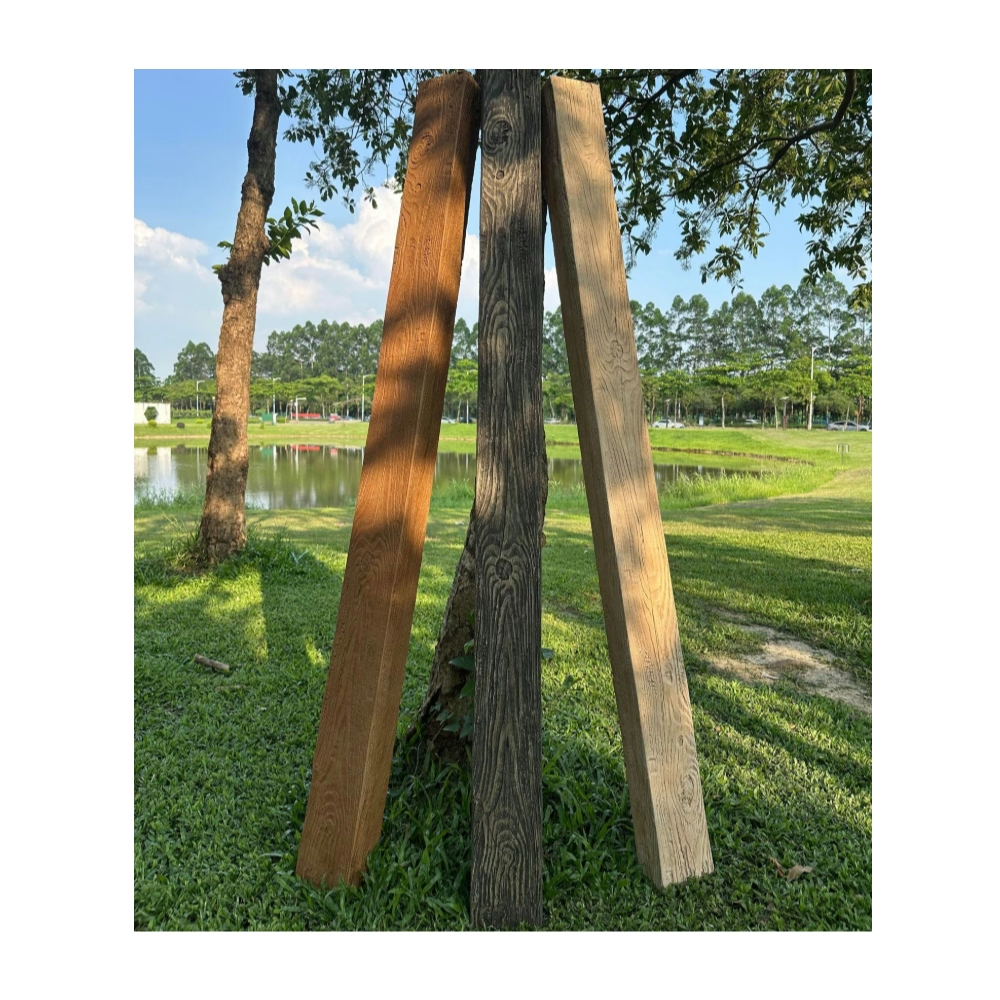
Verification and Long-Term Security
Testing completed connections verifies that installations meet requirements. Gently pulling on beams after installation checks for any movement that would indicate inadequate fastening. Connections should feel solid with no movement detectable. Any movement discovered should be addressed immediately, either by tightening existing fasteners or adding additional attachment points.
Adhesive supplementation adds insurance against long-term loosening. Construction adhesive applied to the mounting surface before beam installation creates a secondary bond that maintains connection even if screws loosen over time. This combination approach provides redundancy that protects against failure from either cause alone.
Documentation of fastener locations assists future maintenance and modifications. Knowing where beams are fastened helps when access is needed for repairs or when modifications require temporary removal. Simple sketches or photographs that indicate screw locations provide this information without requiring invasive investigation.
Technical References
ASTM standards cited in every specification
Test Data
Lab results from internal testing program
Updated 2026
Reviewed against current product specs


