Contractors who specialize in interior finishing know that ceiling beam installations can make or break a project's aesthetic outcome. When the installation goes smoothly, the beams transform the space and the client is delighted. When something goes wrong—beams are misaligned, mounting fails, or the finish is damaged during installation—the cost in time, materials, and reputation can be substantial. This guide addresses the complete installation process for polyurethane faux beams from a professional contractor's perspective, covering techniques and considerations that experienced installers know but that are rarely documented in one place.
Site Assessment Before Installation Begins
Every successful beam installation begins with a thorough site assessment. Arriving at the site without understanding the existing structure leads to surprises that delay the project and erode profit margins.
The first step is to determine the ceiling structure type. Flat drywall ceilings over wooden joists are the most common scenario and offer the most straightforward mounting approach. Vaulted or sloped ceilings with exposed rafters require a different mounting strategy. Suspended tile ceilings require verification that the suspension system can support the load of decorative beams, or an independent mounting framework must be designed and installed before the beams go up.
Check the joist layout carefully. Use a quality stud finder with deep-scan capability to locate joist centers, edges, and any existing mechanical systems running through the ceiling cavity. Mark all joists clearly with painter's tape, not pencil—the tape remains visible through the dust and debris of installation work. For new construction or renovation projects where the ceiling is not yet finished, the joist layout should be documented from the framing stage and cross-referenced during installation planning.
Verify that the ceiling plane is level and uniform. Significant deviations in the ceiling surface—more than 10 millimeters over a 3-meter span—should be addressed before beam installation. Small variations can be compensated with shims behind the mounting hardware, but larger irregularities require more substantial intervention. Document any areas requiring shimming and prepare shim packs of the appropriate thickness before beginning installation.
Assess the load capacity of the ceiling structure. While polyurethane beams are lightweight compared to timber, the cumulative weight of multiple beams with mounting hardware and any accessories must be supported reliably. Calculate the total load per mounting point and confirm that the ceiling joist structure can handle it. In older homes with questionable joist condition, err on the side of more mounting points with smaller spacing rather than fewer points carrying higher loads.
Mounting Methods Compared
Professional installers typically use one of three primary mounting methods, chosen based on ceiling type, beam size, and the client's requirements for the finished appearance.
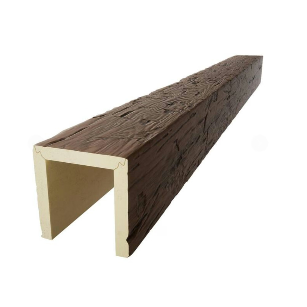
The ledger board method is the most common for flat drywall ceilings. A solid wooden ledger—typically 50 by 100 millimeters or 50 by 150 millimeters—is fastened directly to the ceiling joists with lag bolts. The beam is then placed over the ledger and secured with screws through the beam web. This method provides excellent load distribution, is easy to level, and the mounting hardware is completely concealed within the beam cavity. For beams that will appear to rest on the ceiling surface, the ledger is painted to match the ceiling before the beam is installed.
The bracket and hanger method uses steel angles or C-channel hangers attached to joist sides rather than the bottom. This approach is useful when beams must be mounted close to the ceiling surface without a visible gap, or when the beam cavity is too narrow to accommodate a full ledger board. The brackets are concealed by the beam once installed, but the installation tolerance is tighter—beams must be positioned precisely to cover the brackets completely.
The suspended mounting method is used for very large or heavy beams, or when the ceiling structure cannot support the load. An independent steel framework is hung from the structural ceiling or roof structure using threaded rod or aircraft cable. The beams are then attached to this framework from within their interior cavities. This method requires more coordination during the design phase but provides the most secure and flexible mounting solution for challenging scenarios.
Handling and Positioning Long-Span Beams
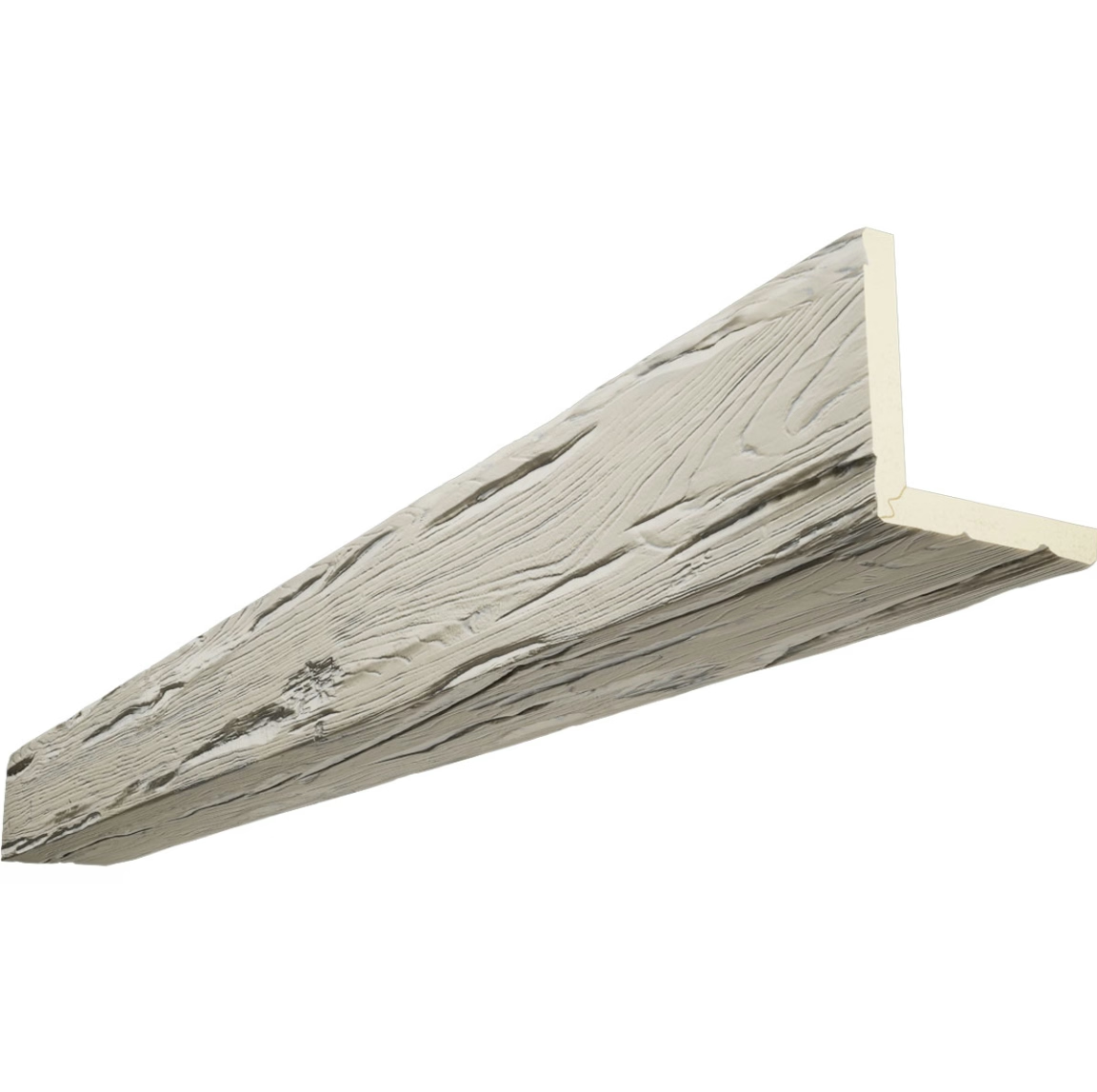
Beams spanning more than 2,400 millimeters present specific handling challenges that require planning and the right equipment. Two-person lifts are essential for beams over 2,000 millimeters in length; single-person installation of long beams risks both personal injury and beam damage.
Before lifting any beam, confirm that the mounting hardware along the entire span is installed and level. It is far easier to adjust mounting hardware before a beam is in place than after. Run a chalk line along the ceiling to mark the centerline of each beam, and use a long straightedge to verify that the mounting surface is level across the entire span.
When lifting a long beam, position yourself and your helper at the quarter points rather than the ends. This reduces deflection and gives better control during placement. Lift the beam just high enough to clear the mounting hardware, slide it into final position, then lower it carefully onto the ledger. Have a third person check the alignment from below as the beam is being positioned.
Temporary bracing may be required for long beams while adhesive sets. A simple T-brace constructed from a 2 by 4 can be wedged between the beam and the floor, holding the beam in position while the construction adhesive bonds. Remove the brace once the adhesive has fully cured—typically 24 hours for polyurethane construction adhesive—after verifying that the beam is secure.
Sealing, Finishing, and Quality Control
The final stage of installation involves sealing, finishing, and a systematic quality control review. This is where the difference between a good installation and an excellent one becomes apparent.
All gaps between beams and the ceiling plane should be sealed with paintable caulk before any painting or staining is done. Run a continuous bead of caulk along the top edge of each beam where it meets the ceiling, smoothing it with a wet finger or a caulk finishing tool. This step prevents dust and air movement through gaps and creates the appearance of a seamless bond between beam and ceiling.
Where beams meet walls or other terminations, apply flexible sealant around the perimeter of the end cap or trim piece. The small gap between a beam end and a wall surface is natural given the dimensional tolerances of both elements, and a properly sealed joint prevents the gap from opening up over time due to seasonal movement in the building structure.
A thorough quality control inspection should cover the following checklist: all beams are level and aligned; spacing is consistent across the installation; all mounting hardware is concealed; all screw holes are filled and finished; all joints between beam sections are tight and properly finished; end caps and trim pieces are secure and properly aligned; no gaps are visible at beam-to-ceiling or beam-to-wall junctions; and the overall appearance is consistent in color and texture from all normal viewing angles.
Document the completed installation with photographs from multiple angles, including close-up shots of joints, end terminations, and any areas where special conditions were handled. These photographs serve as a record of the installation quality and can be invaluable if any future service or repair work is required.
A professionally installed ceiling beam system should perform flawlessly for decades with no maintenance beyond occasional dusting. The combination of precision in planning, care in mounting, and attention to finishing details is what produces that outcome consistently.
Technical References
ASTM standards cited in every specification
Test Data
Lab results from internal testing program
Updated 2026
Reviewed against current product specs


