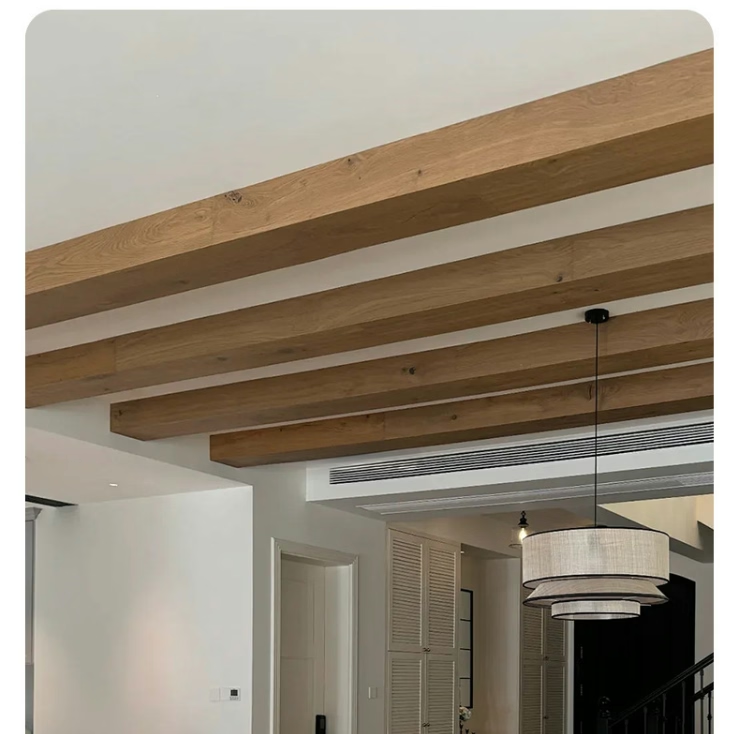
The relationship between weight and safety in seismic design is counterintuitive to many people. Heavier feels safer—we associate substantial weight with stability and permanence. In earthquake engineering, the opposite is often true. Heavier building components attract larger seismic forces, creating greater demands on the structures that support them. A ceiling full of heavy timber beams experiences far greater dynamic loads during ground motion than an equivalent ceiling with lightweight polyurethane beams.
This principle has driven significant innovation in decorative ceiling products for seismic regions. Manufacturers of polyurethane faux beams have developed specifically engineered systems that take full advantage of the material's light weight while meeting the rigorous safety requirements of building codes in earthquake-prone areas. Understanding how these systems work helps architects, engineers, and building owners make informed decisions about ceiling design in seismic zones.

The Physics of Seismic Forces on Ceiling Components
To understand why lightweight materials improve seismic safety, it helps to understand how earthquakes create forces on building components. Seismic forces are inertia-based: when the ground accelerates, building components resist the motion due to their mass. The force required to accelerate a component is proportional to its mass—the more mass, the greater the force.
A 10-foot genuine timber beam weighing 100 pounds attracts 100 pounds of seismic force per unit of acceleration. An equivalent polyurethane faux beam weighing 20 pounds attracts only 20 pounds of force. The attachment system holding the lightweight beam experiences one-fifth the force that would act on the genuine timber beam.
Building codes express seismic design forces as a fraction of the component's weight. A building in seismic zone 4 might experience forces equal to 100% to 150% of the component weight. At these levels, the difference between 100 pounds and 20 pounds translates directly to dramatically different attachment demands. The heavy beam requires expensive, robust attachment systems; the lightweight beam needs much simpler solutions.
Polyurethane Material Properties and Seismic Performance
Beyond light weight, polyurethane material properties contribute to seismic performance in several ways. The material's ductility allows it to deform without fracturing under load. Where brittle materials like plaster or concrete might crack and fail suddenly, polyurethane deflects and absorbs energy gradually.
Polyurethane's resilience allows it to return to its original shape after deformation. An impact or seismic movement that deforms a polyurethane beam temporarily does not necessarily damage it permanently. This characteristic provides margin against overloads that might permanently damage less resilient materials.
The homogeneous nature of molded polyurethane means there are no grain planes, knots, or other structural weaknesses that could fail under seismic loading. Genuine timber beams have internal grain structures that can create planes of weakness. A beam that looks solid may have hidden vulnerabilities that earthquake forces expose. Polyurethane's consistent material properties eliminate these hidden risks.
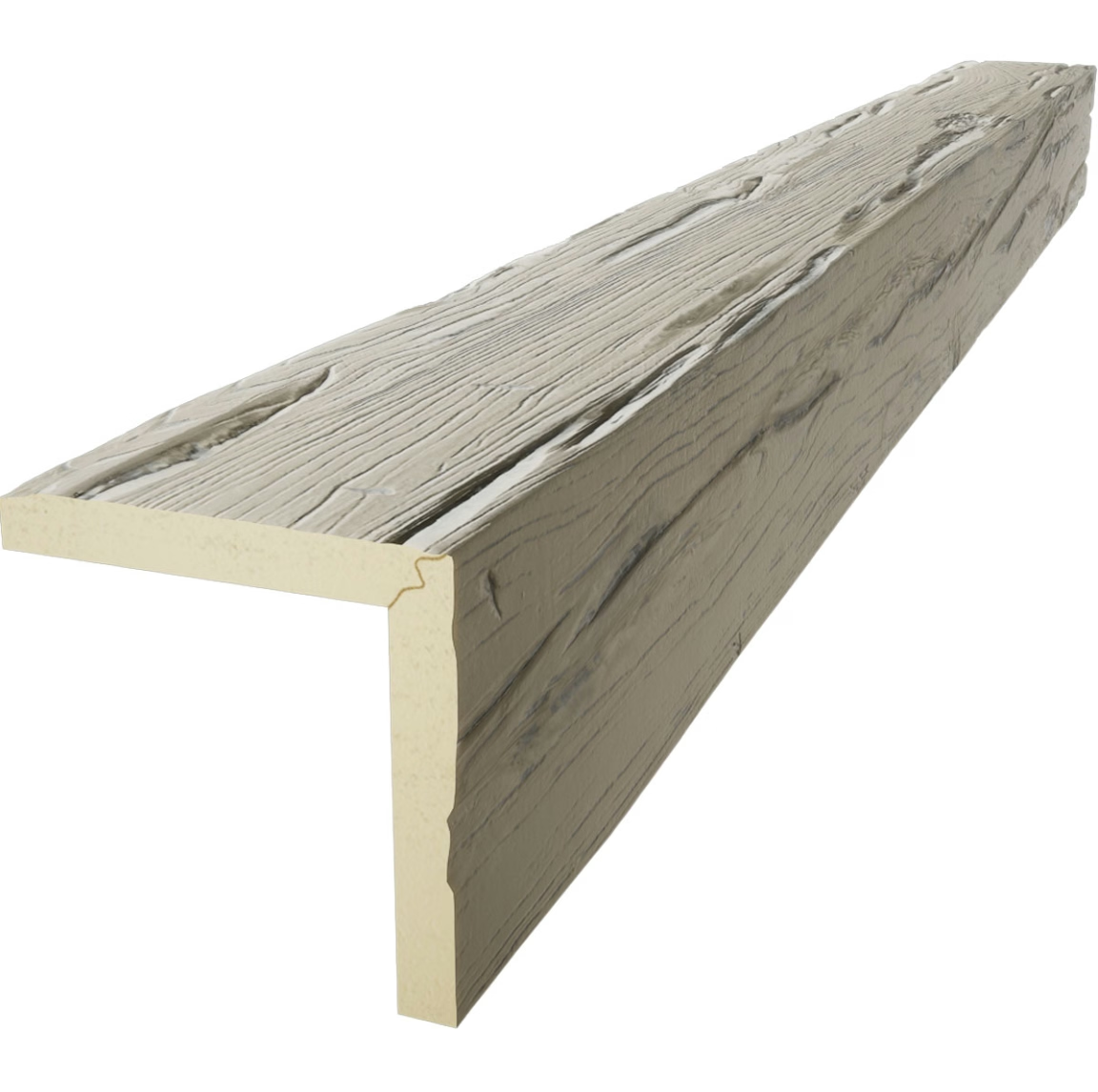
Engineering Design for Seismic Compliance
Seismic-compliant beam design follows engineering principles that balance aesthetic requirements with safety requirements. The design process begins with defining the seismic design parameters: building location, occupancy category, and applicable building code requirements. These parameters determine the seismic forces that the ceiling system must resist.
System design distributes loads through a complete load path from the beam to the building structure. Each connection in this path must be designed for the loads it will experience. The weakest link in the load path determines the system's overall capacity. Engineering analysis identifies potential weak links and sizes them appropriately.
Performance criteria define how the system behaves under seismic loads. Acceptable performance might mean the beams remain attached and functional after a design earthquake. Enhanced performance might require the system to return to its original position and require no repair after the event. Higher performance requirements drive more sophisticated engineering solutions.
Primary and Secondary Attachment Systems
Seismic-compliant installations use a two-level attachment approach: primary attachments carry normal loads and design seismic loads, while secondary attachments prevent falling if primary attachments fail. This redundancy ensures that even if the primary system is overwhelmed, the secondary system prevents beams from falling into occupied spaces.
Primary attachments connect beams directly to the building structure through engineered connections. The connection type depends on the beam weight, the structural system, and the anticipated loads. Common primary attachment methods include lag screws into wood blocking, toggle bolts into hollow structures, and wedge anchors into concrete.
Secondary attachment systems typically use aircraft cable or steel straps that engage only if primary attachments fail. Safety cables mount from the beam to structural elements above, limiting how far a beam can fall if it separates from its primary attachment. The safety cable is sized to support the beam weight with a safety factor of at least 2.
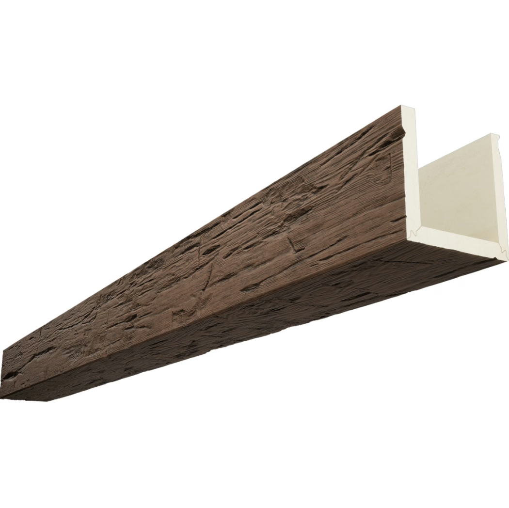
Load Path Integrity and Connection Design
The load path concept is fundamental to seismic engineering. Every force must travel through a continuous path from where it originates to where it is resolved. For ceiling beams, the load path runs from the beam through the attachment hardware to the building structure. Gaps or weaknesses anywhere in this path create failure risk.
Connection design ensures that the load path remains continuous under seismic loading. Connections must resist tension, shear, and moment forces that act simultaneously during earthquakes. Single-direction connections that work under gravity loads may fail under the multidirectional forces of seismic events.
Connection hardware selection accounts for material compatibility, corrosion resistance, and load capacity. Hardware must be compatible with both the beam mounting system and the building structure. Corrosion-resistant materials ensure that connections maintain capacity over the building's lifetime. Load capacities must include safety factors specified by applicable codes.
Testing and Validation of Beam Systems
Physical testing validates engineering predictions about seismic performance. Shake table testing applies realistic earthquake motions to beam installations, measuring response including acceleration, displacement, and attachment loads. Testing continues until the system reaches its failure point, establishing the ultimate capacity.
Cyclic load testing applies repeated loading that simulates earthquake force patterns. Real earthquakes impose multiple cycles of loading and unloading; testing must verify that the system performs adequately through these cycles without degradation. A system that survives the first cycle but fails the fifth has not demonstrated adequate seismic performance.
Finite element analysis (FEA) uses computer modeling to predict stress distributions and deflection patterns under seismic loads. FEA complements physical testing by revealing behavior at points that instrumentation cannot easily measure. The combination of physical testing and computer analysis provides comprehensive understanding of system performance.
Applications Across Building Types
Healthcare facilities represent the highest-consequence applications for seismic-compliant beams. Hospitals must remain functional after earthquakes to treat injuries and save lives. Ceiling failures that drop beams into operating rooms, emergency departments, or patient care areas create catastrophic consequences. Seismic-compliant beams are not optional in healthcare—they are essential infrastructure.
Educational facilities house children and young adults who have limited ability to protect themselves during earthquakes. Schools in seismic zones face some of the most stringent non-structural component requirements. Decorative beams in school auditoriums, gymnasiums, and common areas must meet full seismic compliance requirements.
Commercial office buildings, retail spaces, and hospitality venues in seismic zones must also meet code requirements for ceiling components. While the consequences of failure in these spaces may be less severe than in healthcare or education, occupant safety remains paramount. Code-compliant installations protect both occupants and building owners from liability.
Retrofit and Upgrade Opportunities
Many existing buildings have decorative beam installations that predate current seismic code requirements. These installations can be upgraded to meet current standards through targeted interventions that improve safety without requiring complete replacement.
Safety cable retrofit provides secondary restraint to existing beam installations with minimal modification. Installers access the ceiling cavity, attach aircraft cable from the beam to structural elements above, and adjust the cable length to limit falling distance. This retrofit addresses the most serious risk—beam falling—without modifying primary attachments.
Attachment upgrade replaces or supplements existing primary attachments with code-compliant systems. This retrofit may require removing beams to access attachment points and installing new backing or hardware. The scope of work depends on the condition of existing installations and the specific code requirements applicable to the building.
Assessment by a qualified engineer determines which retrofit approach is appropriate for a specific building. The assessment considers the building's seismic zone, occupancy type, existing beam installation, and available access. The engineering report provides the documentation needed to plan and execute appropriate upgrades.
Economic Considerations for Seismic Compliance
Seismic-compliant beam systems cost more than non-compliant alternatives due to additional engineering, testing, and hardware. However, the cost difference is modest compared to the liability exposure from non-compliant installations and the remediation costs if code violations are discovered.
Building owners who neglect seismic compliance in earthquake zones face potential liability for injuries or deaths caused by falling ceiling components. Jury awards and settlements in earthquake-related cases have reached into tens of millions of dollars. The cost of compliant installation is negligible insurance against this exposure.
Some jurisdictions offer incentives for seismic upgrades that go beyond code minimums. Voluntary seismic improvements may qualify for tax benefits, reduced insurance premiums, or permit fee reductions. Building owners planning renovations should investigate whether available incentives apply to their projects.
Documentation and Record Keeping
Code compliance requires documentation that demonstrates the installed system meets applicable requirements. This documentation package typically includes engineering calculations, product data sheets, installation instructions, and inspection records.
Engineering calculations document the basis for the attachment system design. The calculations reference applicable code provisions, identify design loads, specify connection details, and demonstrate that the proposed system meets all requirements. Calculations should be stamped by a licensed structural engineer when required by local jurisdiction.
Product data sheets confirm that the selected beams and attachment hardware meet the specifications assumed in the engineering calculations. Substitutions may invalidate the engineering compliance; any product changes require re-evaluation by the responsible engineer.
Inspection records document that the installation was completed in accordance with the approved plans. Final inspection by the building department verifies code compliance before occupancy. These records protect building owners by confirming that the installation met all requirements.
Technical References
ASTM standards cited in every specification
Test Data
Lab results from internal testing program
Updated 2026
Reviewed against current product specs