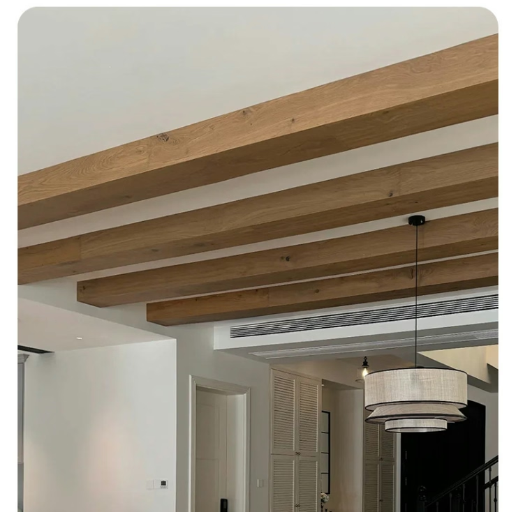
Modern buildings are dense with infrastructure. The ceiling of a contemporary home or commercial space may carry power cables, data networking cables, audio-visual wiring, low-voltage lighting controls, and HVAC ductwork, all competing for space in a plane that is also expected to look attractive. The tension between infrastructure requirements and aesthetic goals is one of the persistent challenges in interior design, and it is particularly acute in spaces with exposed ceilings where there is no dropped ceiling to hide behind.
PU faux beams offer a solution that treats infrastructure as an opportunity rather than a constraint. By incorporating cable management pathways into the beam design, the beams serve double duty: they provide the visual warmth and architectural interest that makes them desirable in the first place, while simultaneously providing a concealed routing system for the cables that the building needs to function.
The Integrated Cable Management Approach
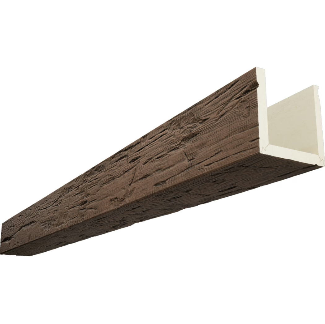
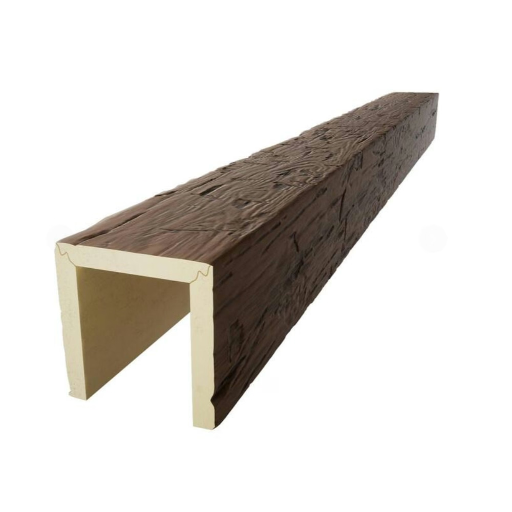
The most effective cable management systems for PU beams are integrated during manufacturing rather than added after installation. A beam with a factory-formed hollow core running its full length provides a continuous pathway for cables that is completely concealed once the beam is installed. Cables enter the core at one end, travel the length of the beam, and exit at any desired point through access ports that are sized and positioned during manufacturing.
This approach has significant advantages over field-installed cable management solutions. The hollow core is sized and shaped to accommodate cable bundles without crowding, and the factory-formed surfaces are smooth and consistent, reducing the risk of cables being damaged by sharp edges or rough surfaces. The access ports are positioned and sized precisely, eliminating the need for on-site drilling that can damage the beam surface or create unsightly openings.
Some manufacturers offer beam systems with multiple discrete channels, allowing different cable types to be routed separately within the same beam. This separation is valuable in commercial applications where power and data cables must be kept apart for signal quality or code compliance reasons.
Planning the Cable Routing Strategy
Effective cable management in beam systems requires planning that begins before the beam installation, ideally during the early design stages of the project. Every cable that will need to traverse the ceiling plane should be identified, mapped, and assigned to a specific beam in the system.
Begin by listing all the devices or systems that will require ceiling-level cable routing. In a residential context, these might include overhead lighting fixtures, ceiling-mounted speakers, television displays, wireless access points, home automation controls, and any devices that are positioned on or near the ceiling. In commercial applications, the list expands to include fire alarm systems, emergency lighting, security cameras, and building automation infrastructure.
For each cable, determine its origin point, its destination, and the most direct route between them. The route should follow beam lines where possible, using the beam hollow cores as the primary routing pathway. Cables that need to transition between beam lines can do so at beam ends or at access points, but the transition should be planned to minimize cable bends and to avoid creating congestion at junction points.
Label every cable at both ends before it is routed through the beam system. Once inside the beam, a cable without a label is extremely difficult to identify without removing it. Pre-labeled cables eliminate this problem and make future modifications, additions, and troubleshooting far simpler.

Code Compliance for Concealed Cable Routing
Building codes regulate the installation of electrical cables in concealed spaces, and the requirements vary by cable type, building use, and jurisdiction. Understanding these requirements before designing the beam cable management system is essential to avoid costly corrections after installation.
Low-voltage cables, including data networking cables (Cat5e, Cat6, Cat6a), coax, speaker wire, and audio/video cables, are generally regulated less stringently than power cables. However, they may still be subject to requirements regarding maximum fill ratios in enclosed spaces, minimum bend radii, and separation from power cables. Consult the applicable standards for your cable type and building jurisdiction.
Power cables in concealed installations typically must be installed in accordance with the same requirements that apply to power cables in walls, which may include using specific cable types rated for concealed installation and maintaining minimum clearances from other building elements. In some jurisdictions, a hollow beam channel may qualify as a raceway, which changes the applicable code requirements.
For commercial installations, the Americans with Disabilities Act and local fire codes may impose additional requirements on cable routing in ceiling cavities. Cables must not block or reduce the capacity of return air plenums, and cables in fire-rated ceiling assemblies may need to be installed in conduit to maintain the assembly's rating.
Working with a licensed electrician or a registered low-voltage installer during the planning phase is the best way to ensure that the beam cable management system meets all applicable code requirements. The cost of professional planning is minor compared to the cost of correcting a non-compliant installation.
Installation Sequence for Cable-Ready Beam Systems
The installation of cable-ready beam systems follows a specific sequence that protects the cables and ensures a clean result. Begin by installing all ceiling hardware—mounting clips, cleats, and support structures—before any cables are routed. This allows full access to the ceiling plane for cable installation without the beam in the way.
Run all cables through the ceiling space before installing the beams, routing them along the paths that the beams will eventually cover. Use cable ties or clips to secure the cables to the ceiling structure at regular intervals, preventing them from sagging or shifting after the beams are installed. At this stage, leave extra cable length at termination points to allow for connection and future service.
With all cables in place and secured, begin installing the beams over the cable routes. Feed the cable ends through the beam access ports as you seat each beam, leaving enough slack at each end for the connections. Work from one end of the beam run to the other, feeding cables through ports as you go.
After all beams are installed and confirmed to be level and properly seated, make the cable connections at each termination point. Apply labels to all cables at this stage if not done earlier. Test each cable run to verify connectivity before closing up access points and completing the trim installation.
Maintenance and Modification of Beam Cable Systems
The concealed nature of beam cable systems creates the primary challenge of reduced accessibility. If a cable fails or a new cable needs to be added, accessing it within the beam system requires either removing the beam or working through access ports that may have limited reach.
Designing the system with adequate access points mitigates this challenge significantly. Access ports at each end of every beam, combined with additional access ports at any junction point or change of direction, allows most cable work to be performed without removing beams. For longer beam runs, intermediate access ports provide reach-in access for cable fishing and troubleshooting.
Documentation is the most important maintenance tool for a beam cable system. A complete as-built diagram showing every cable, its route through each beam, and its termination points is essential for any future work on the system. Without this documentation, modifying or troubleshooting the system requires exploratory investigation that is time-consuming and costly.
Modern buildings demand infrastructure, and infrastructure demands space. Rather than treating this requirement as a limitation, the cable-concealing PU faux beam system turns it into a design asset. The beams become part of the infrastructure solution while maintaining their primary role as architectural elements. The result is a ceiling that looks beautiful and functions expertly, with no visible evidence of the complex systems that make modern building operation possible.
Technical References
ASTM standards cited in every specification
Test Data
Lab results from internal testing program
Updated 2026
Reviewed against current product specs