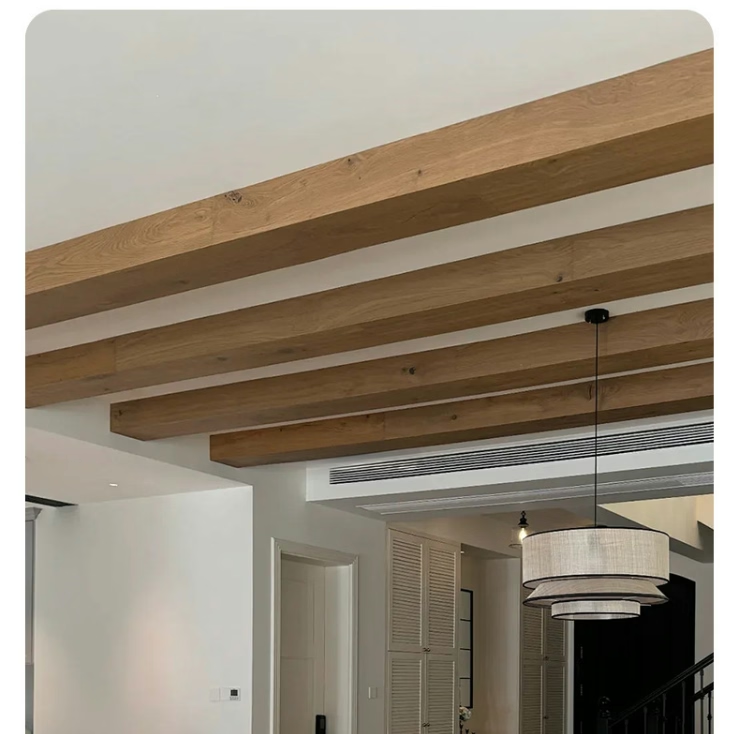
Vaulted ceilings and open-concept floor plans have become defining features of contemporary residential and commercial architecture. The sense of space, airiness, and architectural drama they create is unmatched by conventional flat ceiling designs. But with this visual ambition comes a practical challenge that designers and builders must confront: how do you install beams across spans that can measure twenty, thirty, or even forty feet without creating joints, seams, or visual interruptions that break the desired effect?
The answer lies in splicable beam systems — engineered solutions that allow multiple beam segments to be joined together in a way that is structurally sound and visually seamless. Understanding how these systems work, and what to look for when specifying them, is essential for anyone working on grand-scale ceiling projects.
Why Standard Beams Fall Short in Large Spaces
Most faux wood beams are manufactured in standard lengths, typically ranging from eight to twelve feet for practical manufacturing, shipping, and handling reasons. A single beam of this length is insufficient to span the full width of a large great room, a two-story foyer, or a commercial atrium. In the past, installers would simply butt two beams together at a wall or structural support point, relying on the wall junction to hide the joint.
This approach works adequately in some situations, but in open-concept spaces without internal bearing walls or structural columns, finding a suitable joint location can be difficult or impossible. The result is either a visible seam in the middle of the ceiling span or a beam that must be custom-manufactured in an extra-long length — which creates significant logistical challenges and cost implications.
The Engineering Behind Splicable Systems
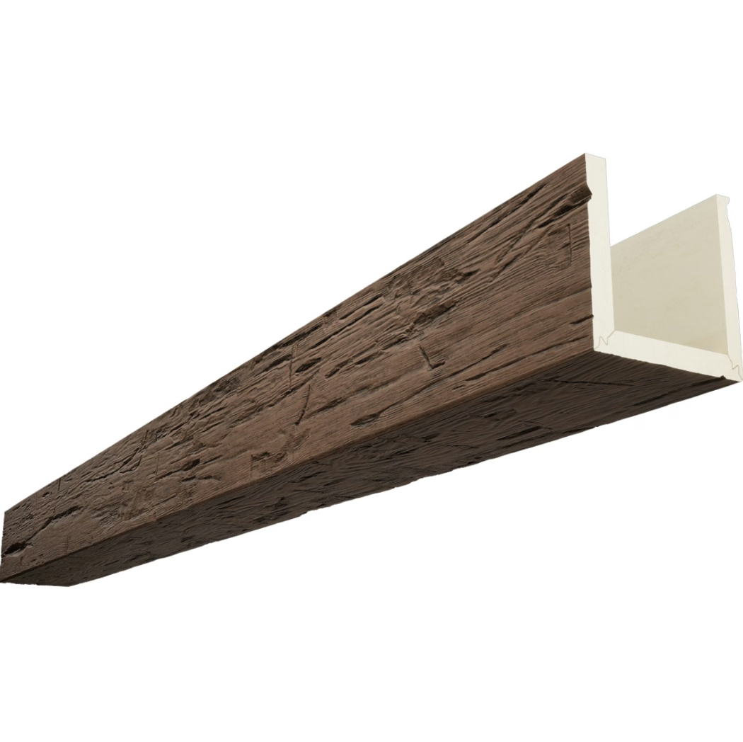
Splicable beam systems address these challenges by incorporating factory-engineered joint mechanisms that allow two or more beam segments to be connected end-to-end with minimal visual evidence of the junction. The joint mechanism itself is typically hidden within the beam's hollow interior or behind a decorative detail such as a beam plate, corbel, or knot overlay.
The structural connection typically involves a metal splice plate or rod that bridges the joint inside the beam, providing load-bearing continuity across the connection. This internal splice transfers any structural loads smoothly from one beam segment to the next, preventing the flexing and movement that could eventually cause a surface crack or separation at the joint. For ceiling installations where beams are primarily decorative rather than load-bearing, the structural requirements are less demanding, but a reliable internal connection is still important for preventing sagging and maintaining surface integrity over time.
The external appearance of the joint is managed through matching surface textures and finishes across the two beam ends. When the joint is positioned over a structural support, a decorative plate or bracket can be installed at the junction point, turning the splice into a design feature rather than something to hide. In spans where no structural support exists at the splice location, careful color matching and texture alignment ensure the joint is difficult to detect from below.


Designing with Splicable Beams
When planning a vaulted or open-concept ceiling with splicable beams, the design process should begin with a careful survey of the available structural support points. Identifying where walls, columns, or roof trusses can bear the load of the beam installation will determine the maximum span between supports and, consequently, the number of splices required.
In some architectural layouts, the structural elements of the building itself can be incorporated into the beam design. Exposed roof truss chords or purlins can serve as the primary structural supports, with decorative PU beams mounted to or wrapped around them. In this configuration, the splicable system spans between the structural points, with the splice joints positioned directly over the building structure where they are naturally concealed or easily decorated.
For spaces with no internal structural supports — a common scenario in great rooms and open lofts — the beam installation plan must account for the full span. A single continuous beam system with strategically placed splices can create the appearance of a monolithic timber ceiling even in spaces that span forty feet or more. The key is working with the manufacturer to determine the optimal splice locations and ensuring the joint mechanisms are properly engineered for the specific span and loading conditions.
Installation Considerations for Long Spans
Installing splicable beams across long spans requires attention to a few key details that may be less critical in shorter installations. Alignment is paramount — if the two beam segments are not perfectly aligned along their centerlines and at their top surfaces, the joint will be visible and the beam's appearance will suffer. Using a laser level or string line to verify alignment before securing the splice is a step that experienced installers never skip.
Support brackets at each end of the beam run must be appropriately rated for the total span and weight. In longer installations, intermediate support points or hanging cables may be needed to prevent the beam from sagging between the structural attachment points. These supports should be positioned where they will be least visually intrusive — often along a wall line or behind a ceiling feature.
For the joints themselves, follow the manufacturer's specification for torque values on any fasteners and ensure the adhesive used to bond adjacent surfaces is rated for ceiling installations. Temperature fluctuations can cause expansion and contraction in long beam runs, and a properly designed splice system accounts for these movements without transmitting stress to the visible surfaces.

Commercial Applications
Splicable PU beam systems are not limited to residential installations. Commercial spaces such as hotel lobbies, restaurant dining rooms, event venues, and retail showrooms frequently feature the open, dramatic ceiling designs that make these systems so valuable. The lightweight nature of polyurethane beams compared to real timber makes them particularly advantageous in commercial retrofit projects where the existing structure may not be rated for heavy loads.
Trade professionals sourcing products for international projects should verify that the splice system specifications meet local building codes and structural requirements. Load ratings, fire resistance classifications, and seismic performance criteria vary by region, and the manufacturer should provide documentation demonstrating compliance with relevant standards.
Technical References
ASTM standards cited in every specification
Test Data
Lab results from internal testing program
Updated 2026
Reviewed against current product specs