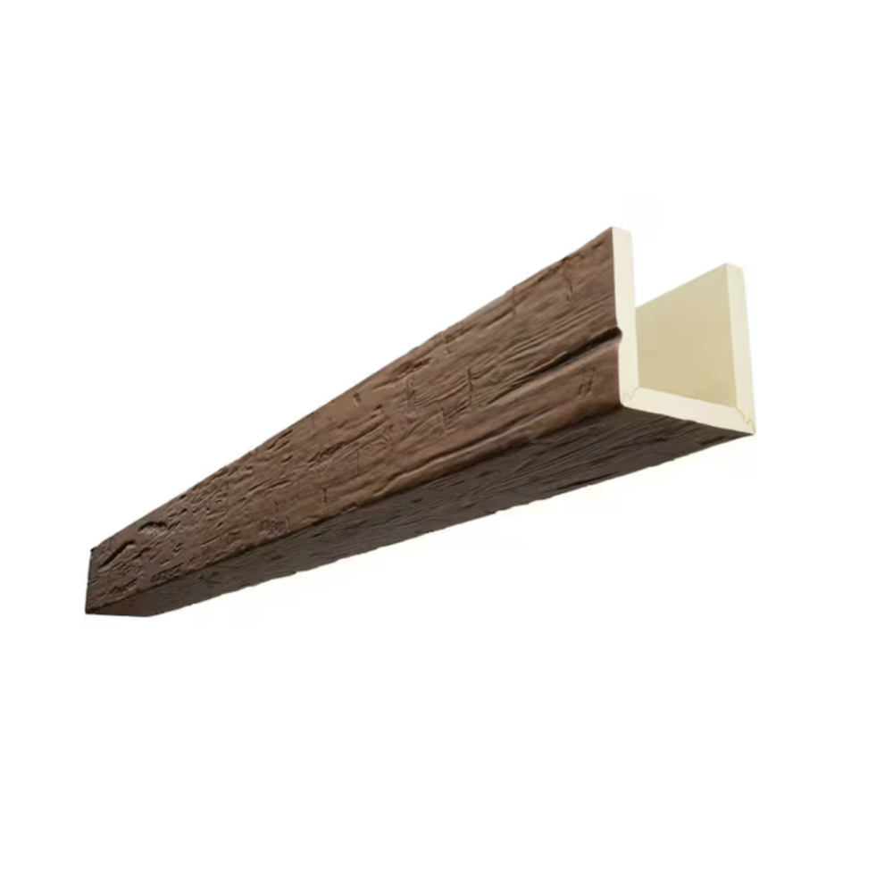
Lighting transforms a room, and few ceiling features benefit from integrated lighting more dramatically than faux timber beams. A beam with carefully placed recessed fixtures creates the effect of light spilling naturally from the timber itself, adding warmth and depth to a space that no surface-mounted fixture can match. For interior designers and trade professionals, understanding how to incorporate lighting cutouts into PU faux beam specifications opens up a powerful design tool.
Why Integrate Lighting Into Beams
The visual logic of integrating lighting into beams is immediately apparent when you see it in a finished space. Light sources hidden within the beam structure create a warm, indirect illumination that eliminates the harsh shadows produced by ceiling-mounted fixtures. The beam itself becomes a source of ambient light, blending its architectural presence with functional illumination in a way that feels organic rather than added on.
From a practical standpoint, beam-integrated lighting also solves the challenge of positioning fixtures in rooms where the ceiling structure or aesthetic prevents surface-mounted installations. In rooms with exposed beam ceilings where drilling into structural timbers is impractical, a PU faux beam with integrated lighting provides the illumination without compromising the design.
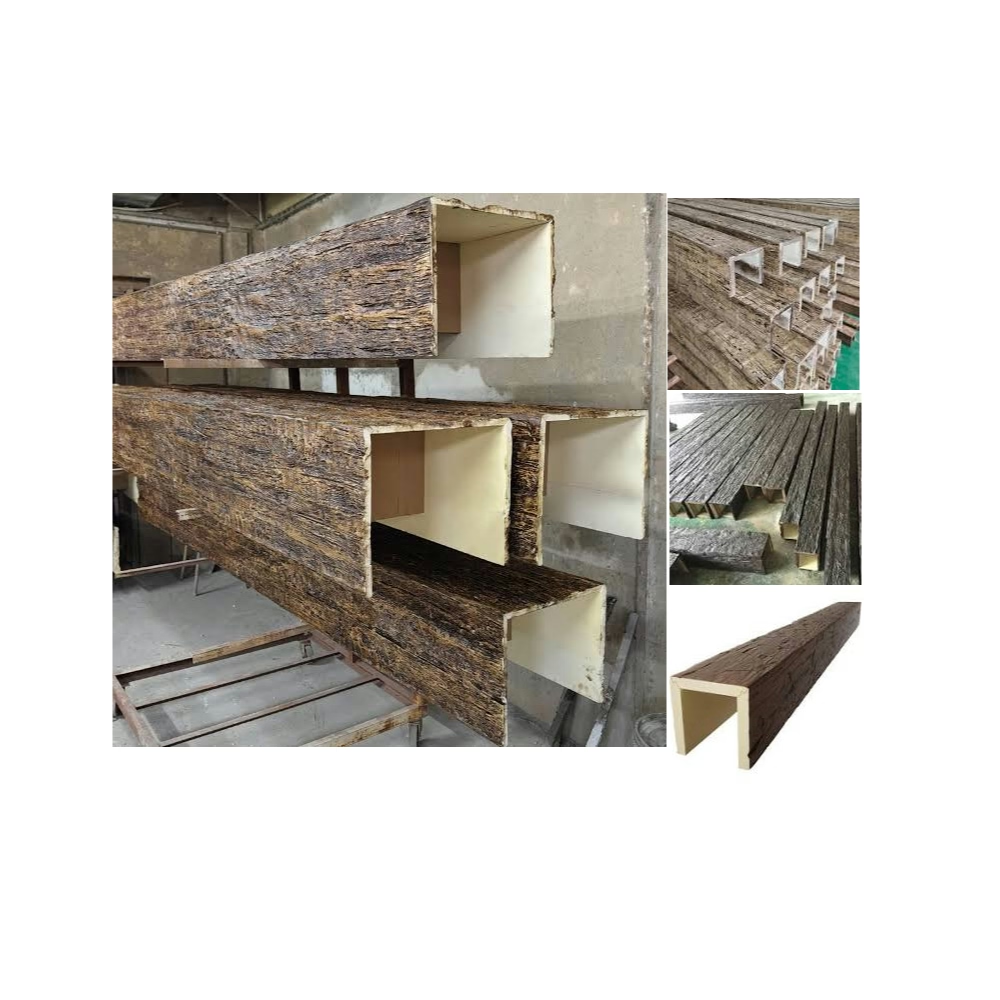
The lightweight nature of polyurethane makes it an ideal substrate for integrated lighting. Unlike real timber, which requires heavy-duty mounting hardware and careful consideration of wiring routes, PU beams can accommodate recessed fixtures with relatively straightforward modifications. The hollow interior of most PU beams provides natural space for wiring and mounting brackets, simplifying the installation process.
Types of Integrated Lighting Configurations
The most common configuration places recessed downlights along the bottom face of the beam, aimed downward to provide task or ambient illumination for the space below. These fixtures are typically positioned at regular intervals along the beam's length, with spacing determined by the desired light distribution pattern and the beam's overall length. Three to four fixtures per beam is typical for ambient lighting applications; more密集 spacing creates a more pronounced lighting effect.
Uplighting configurations aim light upward from the beam's lower surface, creating a wash of light on the ceiling plane above. This approach is particularly effective in rooms with interesting ceiling textures or architectural features — the uplight reveals and enhances these details while adding ambient illumination to the space. Uplights require fixtures with appropriate photometric distribution to avoid creating glare in the occupant's line of sight.
Accent lighting along the beam's sides, achieved through narrow channels cut into the beam's profile, can highlight the beam's texture and three-dimensional form. LED strip lighting placed in these channels creates a subtle halo effect that makes the beam appear to glow. This approach works beautifully in contemporary and minimalist interiors where the beam is intended as a sculptural element.
Designing With Cutout Configurations
Specifying beams with recessed lighting cutouts requires early coordination between the designer, the beam manufacturer, and the electrical contractor. The beam specification must include not only the size and position of each cutout but also the type of fixture to be installed, as different fixtures have different mounting requirements and dimensional specifications.
Cutout size is determined by the fixture's trim diameter plus clearance for mounting hardware. Standard recessed downlight trims range from three to seven inches in diameter, so the corresponding cutouts range from approximately four to eight inches. The manufacturer must also account for the depth of the fixture housing, ensuring that the cutout provides adequate clearance for the entire fixture without compromising the beam's structural integrity.
Fixture spacing along the beam should follow a consistent rhythm that complements the room's proportions. Even spacing creates a formal, orderly appearance; deliberately varied spacing can create visual interest and direct attention to specific areas of the room. In beams that span across multiple rooms or functional zones, the fixture layout may change to reflect the different lighting needs of each zone.
Technical Considerations for Wiring and Heat
Wiring for integrated lighting must be routed through the beam's interior before installation. The hollow space inside most PU beams provides adequate routing for standard low-voltage or line-voltage wiring, but the route must be planned to avoid interference with mounting brackets, splice hardware, and any structural elements that penetrate the beam. Manufacturer collaboration at this stage ensures that the beam is produced with appropriate access holes and internal routing guides.
Heat management is a critical consideration, particularly for fixtures that will be operating for extended periods. LED fixtures generate significantly less heat than incandescent or halogen alternatives, making them the preferred choice for integration into PU beams. If halogen or incandescent fixtures are specified, ensure that the cutout design includes adequate ventilation and that the beam material is rated for the expected thermal exposure. Some manufacturers offer heat-resistant interior coatings for beams that will be used with higher-output fixtures.
Fire safety requirements may also apply, particularly in commercial installations. IC-rated (insulation contact rated) fixtures are designed to be installed in proximity to insulation materials without creating a fire hazard. Confirming that the selected fixtures and beam configuration meet applicable fire codes is a necessary step in the specification process.

Installation Best Practices
The installation sequence for beams with integrated lighting should begin with a complete wiring rough-in before the beams are lifted into position. All wiring should be run, tested, and verified functional before the beams are mounted. This prevents the frustration of discovering an electrical issue after the beam is permanently installed.
Cutouts should be finished with a smooth edge to prevent the fixture trim from being damaged during installation or maintenance. Some manufacturers provide pre-finished cutout edges; others require field finishing. Either way, the cutout edge should be sealed after the fixture is installed to prevent air leakage and to provide a clean transition between the fixture and the beam surface.
After installation, adjust the fixture aim and test the lighting levels to verify that the layout achieves the intended illumination design. The beam's texture and color will affect how light is reflected and distributed, so some adjustment of fixture positioning or output is typically needed to optimize the final result. Document the final fixture positions for future maintenance reference.
Maintenance and Future Modifications
Fixtures installed within beams will eventually require lamp replacement or maintenance. Designing the installation with accessibility in mind simplifies this process. Ensuring that fixture trims can be removed without disturbing the beam's mounting, and that lamp replacement does not require beam removal, prevents routine maintenance from becoming a significant undertaking.
For projects where the lighting layout may need to change over time — in commercial spaces that are periodically reconfigured, for example — consider using adjustable fixtures that can be re-aimed without tools, or providing access panels within the beam that allow fixture replacement without demolition.
Technical References
ASTM standards cited in every specification
Test Data
Lab results from internal testing program
Updated 2026
Reviewed against current product specs