
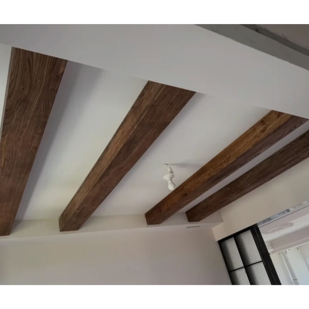
Hollow shell construction is one of the most common manufacturing approaches for PU faux timber beams, offering an excellent balance of visual impact, lightweight handling, and material efficiency. But hollow construction presents a specific challenge that installers must understand and address: the beam's interior is empty space, which means the mounting hardware must create a secure attachment point within that void without relying on the continuous material found in solid beams. Stable bracket systems are the engineered solution to this challenge.
Understanding Hollow Shell Construction
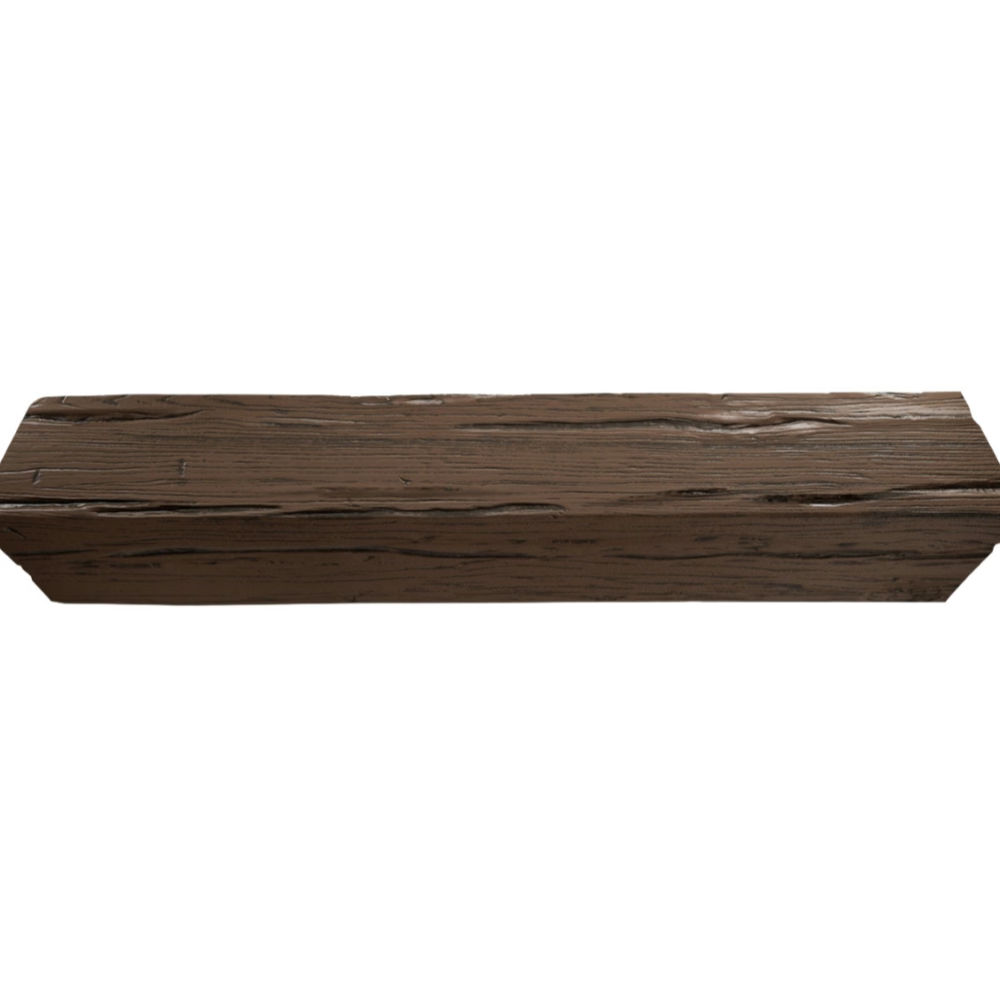
Hollow shell PU beams are manufactured by molding or casting the beam's four sides — top, bottom, and two sides — as separate pieces that are then joined along their edges to create the finished hollow profile. This approach reduces material usage, lowers weight, and makes the beams easier to handle during installation. The resulting interior space, while empty, provides a natural channel for wiring and can accommodate mounting hardware when properly designed.
The wall thickness of a hollow shell beam typically ranges from half an inch to an inch or more, depending on the beam's size and the manufacturer's specifications. This thickness must be understood when selecting mounting hardware, as fasteners and brackets must engage adequately with this wall material to develop their full load capacity. A fastener driven into thin-walled hollow material without appropriate consideration will not develop the hold strength that the same fastener would achieve in solid wood.
Bracket Design Principles
Stable bracket systems for hollow shell beams work by distributing the load from the fastener across a wider area of the beam wall, much like a washer distributes load across a larger surface area of the material being fastened. The bracket's footprint — the area in contact with the inside of the beam — determines how effectively the load is spread.
Several bracket geometries are in common use. Flat mounting plates with multiple fastener locations provide the broadest load distribution and are suitable for heavy loads or long spans. L-shaped brackets combine a mounting plate with a vertical leg that reinforces the beam wall at the point of attachment. Channel-style brackets wrap partially around the beam's interior, engaging both sidewalls and the bottom surface for maximum resistance to pull-out forces.
The material of the bracket itself matters. Steel brackets provide the highest load capacity and are preferred for structural applications or long spans. Aluminum brackets are lighter and easier to handle but may have lower load ratings. Some manufacturers supply brackets as part of a complete installation system, with load ratings tested in combination with their specific beam products.
Calculating Load Requirements
Before selecting brackets, calculate the actual load that will be placed on each mounting point. The total load includes the weight of the beam itself, any finishes applied to the beam, and any additional loads such as light fixtures, ceiling fans, or decorative elements attached to the beam. Divide this total by the number of mounting points to determine the load per bracket.
Apply a safety factor to this calculated load. Professional installations typically use a safety factor of 3:1 or higher, meaning each bracket is rated to handle at least three times the expected load. This accounts for unexpected loads, installation variations, and long-term material changes. Never rely on marginal bracket capacity — when in doubt, use more mounting points or higher-rated brackets.
For beams spanning long distances between support points, the bracket load calculations must also account for the beam's deflection between supports. Long beams deflect slightly under their own weight, and this deflection creates additional pulling forces on the end brackets. Consult the beam manufacturer's load charts or engineering data to determine the appropriate bracket capacity for your specific installation.
Installation Best Practices
Proper bracket installation in hollow shell beams begins with locating the mounting position precisely. Mark the location on both the interior and exterior of the beam to ensure the bracket is centered and aligned correctly. For beams that will receive a finished surface, mark the fastener locations before finishing to avoid drilling through or damaging the completed coat.
Drill pilot holes for the fasteners, using a bit size that is slightly smaller than the fastener's minor diameter. This allows the fastener to engage the material fully while reducing the risk of splitting or cracking the thin wall material. For heavy-duty fasteners or lag screws, drilling a clearance hole through the wall and using a washer to spread the load on the interior surface is recommended.
Apply adhesive to the bracket's contact surfaces before positioning it in the beam. The adhesive provides additional bonding between the bracket and the beam's interior surface, reducing the risk of bracket movement or rotation over time. Use an adhesive that is compatible with both the bracket material and the polyurethane substrate, and allow it to cure fully before applying load to the bracket.
Secure the beam to the ceiling structure using the appropriate fasteners for the substrate. In wood-frame construction, lag screws into the ceiling joists provide the most reliable connection. In steel frame construction, appropriate toggles or beam clamps are required. Verify that the fastener length is adequate to penetrate the structural member with sufficient engagement to develop the full load capacity.
Long-Term Stability and Inspection
A properly installed bracket system should remain stable for the life of the building, but periodic inspection is good practice, particularly in the first year after installation when any settling or adjustment in the structure is most likely to occur. Check that all fasteners remain tight and that no gaps have developed between the bracket and the beam interior.
For commercial installations or multi-story buildings where access to the ceiling is limited, documenting the bracket locations and fastener specifications during installation is essential for future maintenance. A simple diagram showing each beam's mounting points, bracket types, and fastener specifications allows maintenance personnel to address any issues without exploratory investigation.
Technical References
ASTM standards cited in every specification
Test Data
Lab results from internal testing program
Updated 2026
Reviewed against current product specs


