Custom polyurethane faux beam projects succeed or fail based on how effectively design intent translates into manufacturing reality. Technical drawings serve as the primary communication vehicle between designers, manufacturers, and installers, carrying dimensional information, connection requirements, and finish specifications that must be interpreted consistently across all parties. Investment in clear, comprehensive drawings prevents costly revisions and fabrication errors that delay projects and erode margins.
Fundamentals of Effective Beam Drawings
Professional technical drawings for faux beam applications begin with clear identification of the overall project context. Title blocks include project name, drawing number, revision history, and scale information that establishes reference points for all subsequent detail work. Drawing sheet organization follows industry conventions that experienced contractors and fabricators recognize immediately, reducing interpretation time and error potential.
Plan views establish beam locations, orientations, and spatial relationships within the architectural context. Dimension strings communicate centerline-to-centerline relationships and clearances from adjacent elements. Coordinate systems when present enable precise positioning for complex three-dimensional layouts involving intersecting beams, canted installations, or irregular ceiling geometries.
Elevation drawings complement plan information with vertical dimensioning and profile representations. Cross-references between plan and elevation views create complete spatial understanding, enabling fabricators to visualize finished installations without requiring three-dimensional models. Section details extract critical connection areas at larger scales for precise manufacturing and assembly guidance.
Dimensioning Standards and Tolerances
Effective dimensioning practices communicate acceptable variation rather than impossible ideals. Polyurethane fabrication processes introduce inherent dimensional variation that must be accommodated through appropriate tolerance assignment. Standard length tolerances for extruded or molded beams typically fall within ±1/8 inch, while cross-sectional dimensions may vary ±1/16 inch depending on profile complexity and manufacturing method.
Profile drawings should specify critical dimensions that affect fit or appearance separately from non-critical dimensions that may vary freely. Exposed surface dimensions often warrant tighter tolerances than concealed dimensions, while connection points that affect structural performance receive particular attention. Tolerance stack-up analysis for assemblies with multiple mating parts prevents assembly difficulties from accumulated variation.
Geometric dimensioning and tolerancing symbols provide precise communication for critical features when appropriate. Position tolerances for fastener locations, profile tolerances for visible surfaces, and datum references establishing coordinate systems enable unambiguous manufacturing instructions for high-precision applications. However, this precision increases inspection complexity and should be reserved for genuinely critical features.
Connection Detail Standards
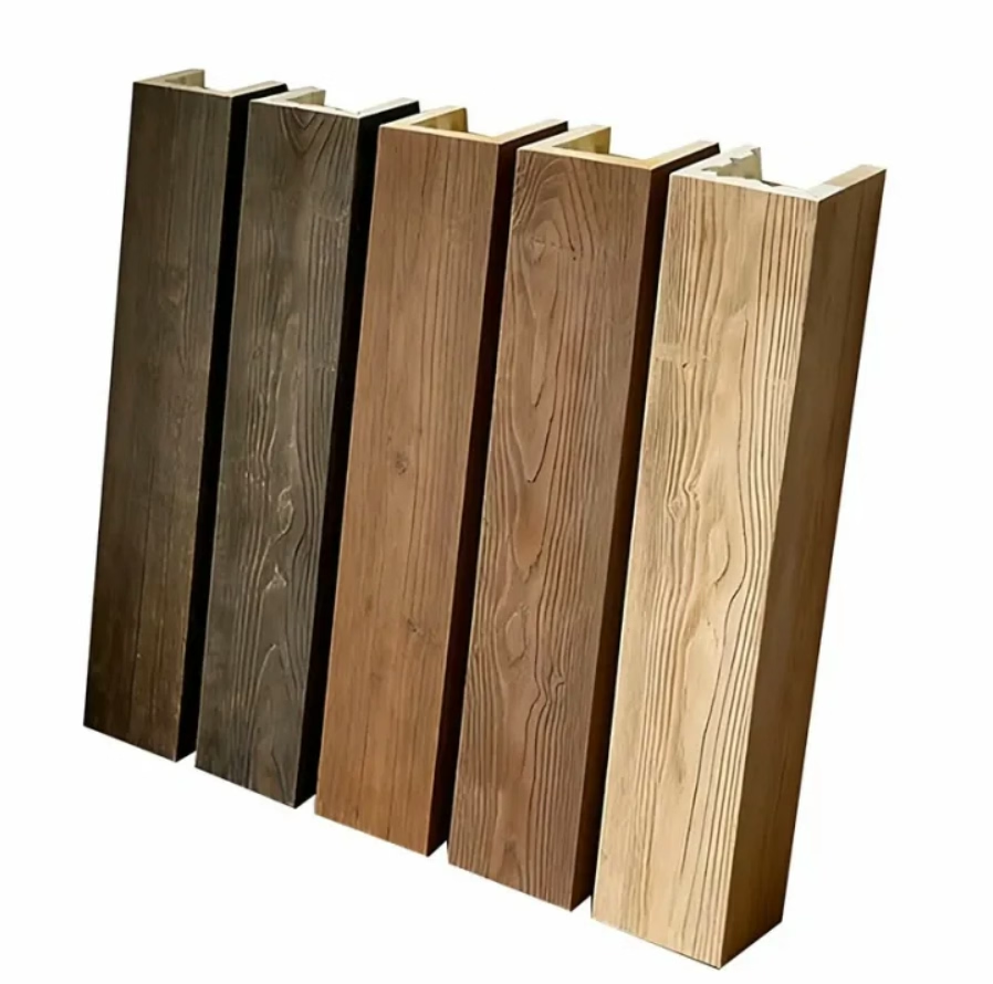
Beam-to-beam connections require detailed drawings that specify configuration, reinforcement, and installation sequence. Splice connections where beam ends meet receive particular attention, with drawings showing scarf angle, adhesive application requirements, and reinforcement plate specifications where used. Crown orientation addressing how beams meet at interior corners needs explicit direction to achieve consistent appearance.
Wall connections present mounting options that drawings must communicate clearly. Cleat configurations, adhesive application areas, and mechanical fastener locations each require specification. Load transfer paths from beam weight through connections to structural supports need verification that current-carrying capacity exceeds beam weight and any applied loads. Support spacing calculations may accompany drawings to justify specified installation intervals.
Ceiling connections for suspended installations involve different hardware and procedures than wall-mounted configurations. Threaded rod diameters, canopy designs, and adjustment ranges receive explicit specification. Seismic or dynamic load considerations may require additional hardware or reinforcement that drawings must indicate. Coordination with structural engineering for ceiling plane modifications typically occurs during design phases, with final connection details reflecting engineering decisions.

Finish and Surface Treatment Specifications
Finish specifications translate design intent into manufacturing requirements that affect both appearance and performance. Base material options for polyurethane typically include smooth surfaces accepting paint well, wood-grain embossed surfaces simulating natural timber, and primed surfaces ready for site finishing. Each option carries distinct cost and lead time implications that drawings should acknowledge.
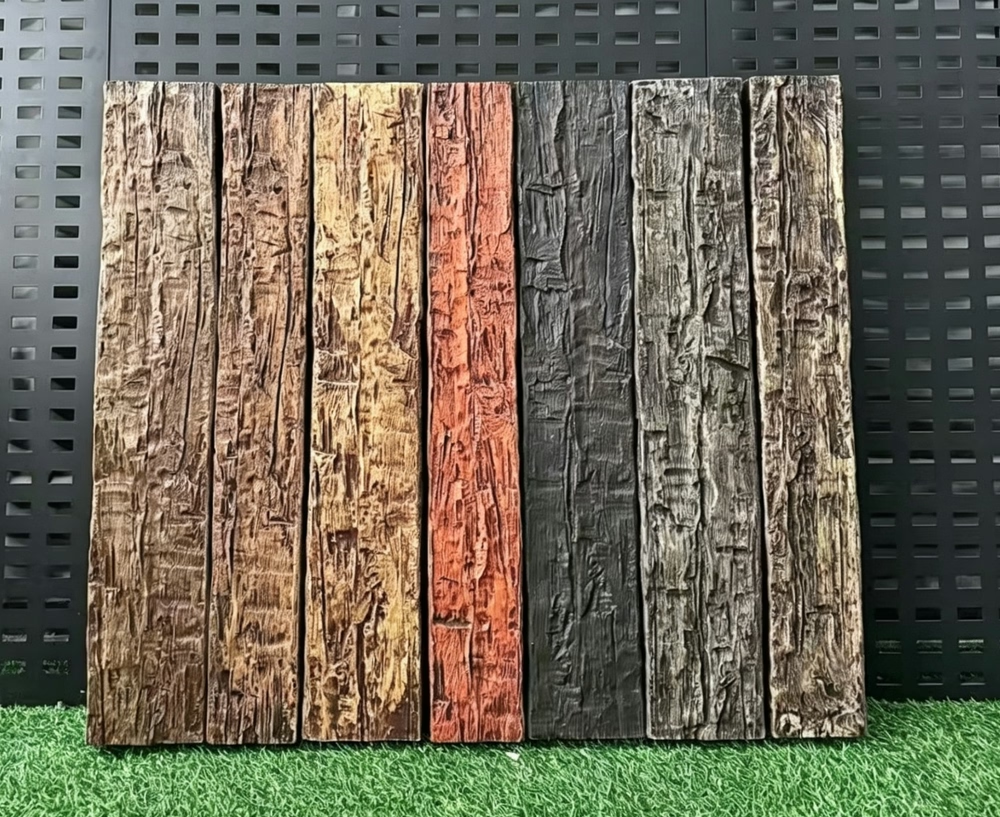
Color and texture specifications require physical or digital references that ensure manufacturing consistency. Reference samples maintained by both designer and manufacturer establish appearance targets for quality verification. Color matching specifications using standard systems such as NCS or RAL enable precise communication for custom finishes. Texture specifications should address both visual appearance and tactile characteristics for applications where surface contact occurs.
Protective finish requirements for different environments receive explicit treatment. Interior installations in controlled environments may require only basic paint or stain coatings, while exterior applications need UV-resistant finishes that prevent degradation. Wet area installations in bathrooms or pool enclosures require moisture-resistant formulations that resist biological growth. Drawings should reference applicable finish standards and specify any required certifications.
Custom Profile Development
Projects requiring non-standard profiles need development processes that convert design concepts into producible specifications. Initial sketches explore form options and identify functional requirements that the profile must satisfy. Iterative refinement through multiple drawing generations progressively resolves dimensional relationships and production feasibility concerns.
Draft analysis evaluates proposed profiles for moldability within acceptable manufacturing tolerances. Undercut features requiring side-action or lift mechanisms increase tooling complexity and unit costs. Wall thickness consistency throughout the cross-section prevents sink marks and warping during production. Radii on interior corners facilitate material flow and reduce stress concentrations. Manufacturing engineering reviews identify production concerns before tooling investment locks in design decisions.
Prototype fabrication using rapid manufacturing methods enables physical evaluation before committing to production tooling. Stereolithography or CNC machining can produce sample pieces for fit assessment and appearance evaluation. Modifications identified through prototype testing refine drawings before production begins, preventing costly changes after tooling completion.
Drawing Sets and Organization
Complex projects require organized drawing sets that guide work systematically from overview to detail. Cover sheets index all drawings with revision dates and approval signatures that document authorization for construction. Drawing sequences follow logical progressions from site plans through building plans to detailed connections.
Drawing hierarchies establish relationships between drawings at different scales. Master plan drawings reference detailed section drawings that provide installation-specific guidance. Section drawings reference standard details that address repeatable connection types. This hierarchical organization prevents duplication while ensuring complete information coverage.
File naming conventions and drawing numbering systems facilitate document management throughout project lifecycles. Unique drawing numbers enable unambiguous reference in specifications, contracts, and correspondence. Version control suffixes distinguish sequential revisions that reflect design evolution. Archive systems preserve historical versions for reference when questions arise about earlier project conditions.
Digital Delivery and Collaboration
Modern practice increasingly favors digital drawing delivery over paper-based distribution. PDF format provides universal accessibility while preserving formatting integrity. Native CAD files enable modification when necessary, though revision tracking becomes essential to prevent unauthorized changes. Cloud-based collaboration platforms centralize document access and provide automatic version synchronization.
Drawing review processes leverage digital tools to streamline approval workflows. Markup and comment functions enable electronic redlining that replaces traditional pencil review marks. Automated comparison functions highlight changes between drawing revisions, focusing review attention on modifications rather than requiring complete re-examination. Digital signatures provide legal equivalence to traditional wet signatures in most jurisdictions.
Coordination with other building systems benefits from digital drawing integration. Clash detection between structural framing, mechanical ductwork, and electrical conduit that beams may intersect requires coordination drawings showing all relevant trades. Early identification of conflicts prevents site modifications that disrupt installation schedules and increase costs.

Quality Control Integration
Technical drawings provide the reference standard against which fabrication and installation quality gets measured. Inspection points defined in drawings enable systematic quality verification at critical stages. Dimensional verification compares actual measurements against drawing specifications using appropriate measurement systems and documented procedures.
Acceptance criteria should align with tolerances specified in drawings and appropriate industry standards. Discrepancies requiring resolution receive documentation that describes conditions, references drawing requirements, and proposes remediation approaches. These deviation reports create records supporting root cause analysis and process improvement initiatives.
As-built documentation captures actual installed conditions for facility management reference. Measured dimensions, hardware specifications, and finish references recorded during installation provide maintenance personnel with accurate information for future work. These records prove particularly valuable when beams require removal for access to concealed building systems.
Professional technical drawing practices transform custom faux beam concepts into manufacturable and installable reality. Investment in drawing quality pays dividends throughout project execution, reducing uncertainty, preventing errors, and enabling efficient collaboration among all stakeholders. Suppliers and contractors who prioritize drawing standards position themselves for consistent project success and satisfied clients.
Technical References
ASTM standards cited in every specification
Test Data
Lab results from internal testing program
Updated 2026
Reviewed against current product specs


