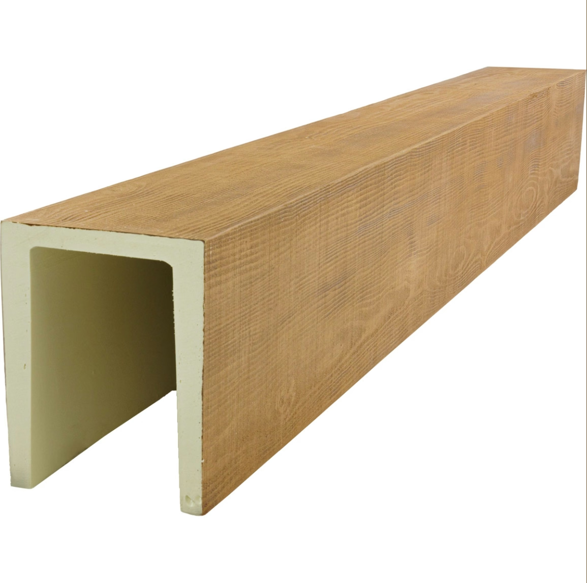
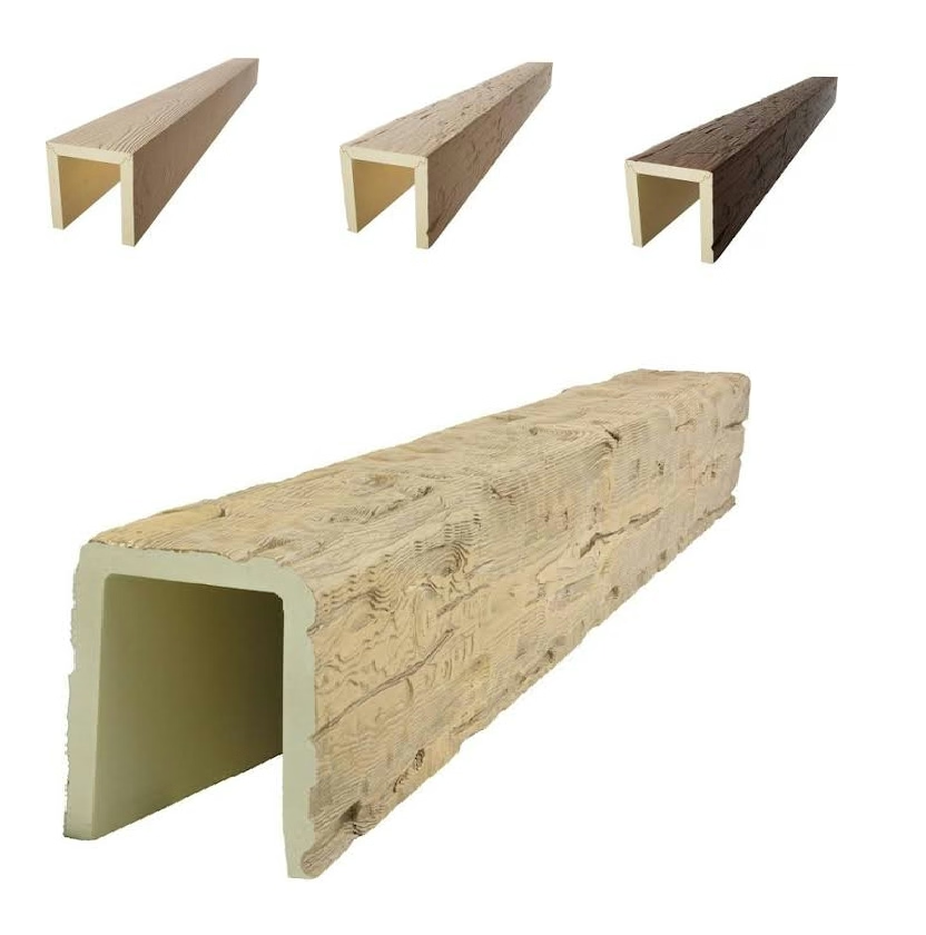
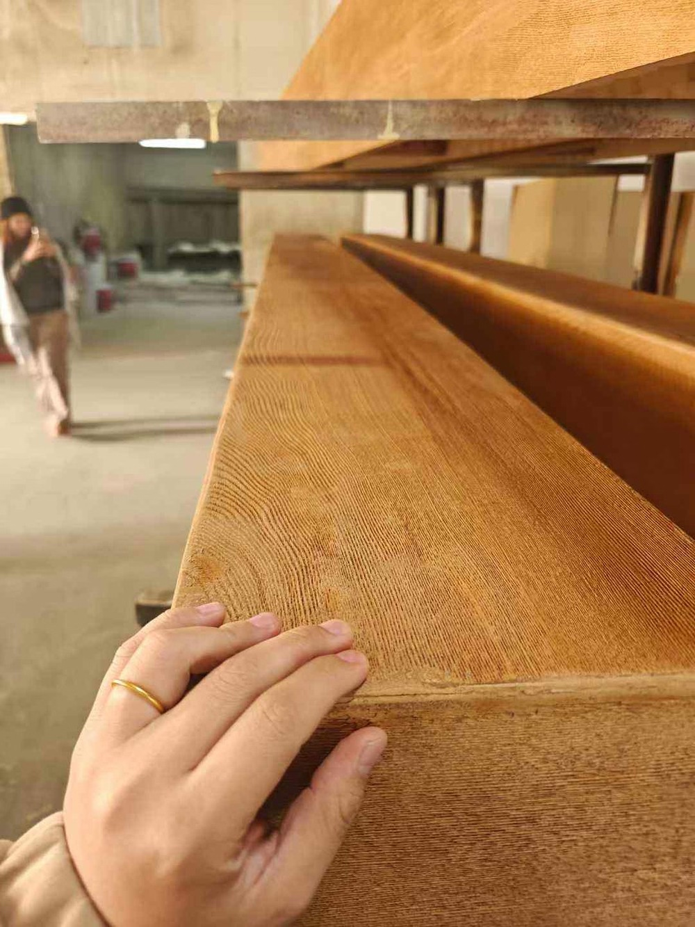
Every custom PU faux wood beam starts with a mold. Not a 3D model, not a render, not a sketch — a mold. The mold is the physical object that determines the beam's shape, its surface texture, its dimensional accuracy, and ultimately its appearance. The quality of the mold determines the quality of every beam that comes out of it.
Developing a new mold for a unique beam profile is a project within a project. It requires decisions that affect cost, lead time, production quality, and durability. This article walks through the process from the initial brief to a production-ready mold, explaining what's involved at each stage and what decisions need to be made.
Starting with the brief
Before a mold can be developed, someone has to define what the beam is supposed to look like. The definition should be as complete as possible at the start, because changes made later in the process are progressively more expensive.
A complete brief for a new beam profile includes:
- Cross-sectional drawing: A dimensioned drawing of the beam profile from all relevant angles. A simple rectangular profile needs a width and height dimension. A complex ornamental profile needs a full section drawing showing all radii, chamfers, and decorative details.
- Length specification: The required beam length, or the maximum length that the production equipment can accommodate. If the project requires beams longer than the factory's standard equipment allows, the mold design may need to accommodate multi-piece production.
- Grain texture specification: The wood species or style of grain texture, the desired scale (fine, medium, coarse), and the grain direction relative to the beam axis. If a custom grain texture is required, a reference sample or image should be provided.
- Finish specification: The base color or stain tone, the number of finish layers (single-tone or multi-tone), and the sheen level. If the finish requires a specific undercoat or primer system, note it.
- Performance requirements: Any fire rating, UV resistance, or structural load requirements that affect the foam formulation. These affect the mold design indirectly (through the resin system) and should be flagged early.
- Volume estimate: The expected order quantity over the mold's lifetime. This affects the choice of mold material and the acceptable amortization of tooling cost.
Stage 1: Engineering review and producibility assessment
The first step in mold development is an engineering review. A technical engineer at the factory examines the brief and assesses whether the proposed profile is producible using standard PU molding methods.
The review covers:
Draft angle requirements
Every mold has a draft angle — a slight taper built into the mold walls that allows the cured part to release without sticking. The standard draft angle for PU foam molds is 1 to 2 degrees per side. Profiles with vertical walls or undercuts require additional engineering to allow clean release.
A chamfered profile (where the corners are cut at an angle) has natural draft. A profile with sharp vertical corners requires machining to a slight taper, which changes the beam's visual profile slightly. The engineer will advise on whether the taper is acceptable or whether the profile needs modification.
Undercut analysis
An undercut is a feature that locks the part into the mold — a groove that goes in rather than out, for example, or a decorative detail that would trap the cured foam against the mold surface. Undercuts require a different mold architecture: sliding mold plates, flexible silicone liners, or a multi-piece mold that assembles around the part.
Undercuts add cost and complexity. If a proposed profile has significant undercut geometry, the engineer may recommend simplifying the profile or accepting a small visual modification that eliminates the undercut.
Wall thickness consistency
The foam must fill the mold cavity completely and uniformly. Areas of the cavity that are significantly thinner than adjacent areas are prone to incomplete fill and voids. The engineer reviews the cross-section for wall thickness consistency and flags any sections that may be difficult to fill.
Surface area and complexity
Large beam profiles have large surface areas. The mold for a 400×400 mm square beam has more surface area than the mold for a 100×150 mm rectangular beam, which means more material to machine and more surface to finish. Complex ornamental profiles add machining time because the 3D geometry has to be reproduced accurately in the mold surface.
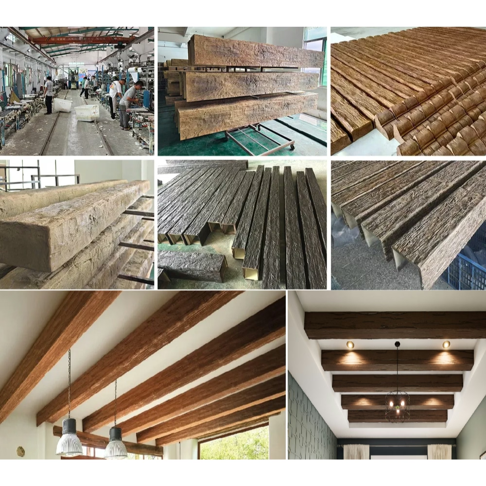
Stage 2: Mold material selection
Once the producibility assessment is complete, the engineer recommends a mold material. The choice of material affects cost, production speed, surface finish quality, and mold life.
Aluminum tooling board
The most common choice for decorative beam molds. Aluminum tooling board is a high-density composite material that machines cleanly, releases PU foam reliably, and produces a smooth surface finish. A tooling board mold for a standard beam profile typically costs $1,500 to $5,000 and has a production life of 200 to 500 pieces.
Tooling board molds are produced by CNC machining from a CAD file. The machining accuracy is ±0.1 mm, which is sufficient for most decorative beam applications.
Machined aluminum
Solid aluminum molds are more durable than tooling board. A machined aluminum mold can be used for high-volume production runs (1,000+ pieces) or for profiles with very fine surface detail that would wear quickly on tooling board. Machined aluminum molds cost 2 to 4 times more than tooling board but last 5 to 10 times longer.
Silicone-lined molds
For profiles with undercuts or complex 3D geometry, a silicone liner inside a rigid outer mold allows the cured part to release without damage. Silicone molds are more expensive and have shorter production lives than rigid molds, but they're the only option for certain profile geometries.
Cast zinc or zamak
For high-volume ornamental profiles, zinc or zamak casting can produce a mold with fine surface detail at moderate cost. The casting process captures surface texture faithfully. Cast molds are slower to produce but have excellent durability.
Stage 3: Master pattern creation
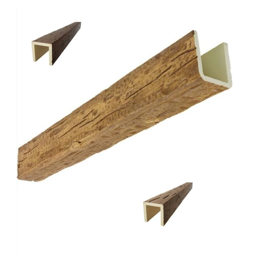
Before the production mold can be made, a master pattern is created — a physical model of the beam that will be used to generate the production mold.
For simple profiles, the master pattern can be CNC-machined directly from the cross-section drawing. For ornamental profiles with hand-carved details, the master pattern requires both CNC machining (for the basic geometry) and hand sculpting (for the fine detail).
The master pattern is the reference object against which the production mold is verified. Any error in the master pattern propagates into the mold and then into every beam produced from the mold. Quality control at this stage is critical.
Stage 4: Mold construction
With the master pattern approved, the production mold is constructed. The construction method depends on the mold material:
CNC machining (for tooling board and aluminum): The mold cavity is machined using a multi-axis CNC mill following the master pattern or the CAD file. After machining, the mold halves are finished, polished, and fitted with clamping hardware and threaded inserts for fasteners.
Casting (for zinc, zamak, or silicone): The master pattern is used as a pattern in a casting mold. Molten metal or liquid silicone is poured around the pattern, capturing the surface texture and geometry. After curing, the pattern is removed and the mold is finished and fitted.
Hand fabrication (rare, for very complex molds): A skilled mold maker builds the mold by hand, using a combination of machining, welding, and hand fitting. This is slow and expensive but allows maximum control over complex geometry.
Stage 5: Trial and validation
The first use of a new mold is a trial, not production. The trial confirms that the mold produces beams that match the design intent.
Trial steps:
- Assembly and clamping: The mold halves are assembled and clamped with the armature (reinforcement core) in place. The clamping force is set to prevent flash (foam squeeze-out at the parting line) without distorting the mold.
- Pour and cure: The PU resin system is mixed according to the specified formula and poured into the mold cavity. The foam rises, skins over, and cures.
- Demolding: The cured beam is removed from the mold. The demolding quality is assessed: does the beam release cleanly? Are there any surface blemishes from the mold release agent? Is the grain texture faithfully reproduced?
- Inspection: The beam is measured against the original specification. Dimensional accuracy, surface finish quality, and grain texture are assessed.
- Modification: Any issues identified during inspection are addressed by modifying the mold — polishing a rough patch, adding shimming to correct a dimensional error, adjusting the release agent system.
The trial-and-modification cycle repeats until the mold produces beams that consistently meet the specification.
Timeline and cost summary
| Stage | Typical duration | What affects duration |
|---|---|---|
| Engineering review | 3-10 days | Profile complexity, completeness of brief |
| Master pattern creation | 5-20 days | Ornamental detail, hand sculpting |
| Mold construction | 10-25 days | Mold material, profile complexity |
| Trial and validation | 5-15 days | Number of trial iterations |
| Total | 23-70 days |
The total timeline for a new mold from brief to production-ready is typically 4 to 14 weeks. Simple profiles with no ornamental detail can be at the low end of this range. Complex ornamental profiles with hand-carved detail can approach the high end.
The cost follows a similar range: $3,000 to $20,000+ for tooling, depending on complexity, material, and the factory's pricing structure.
Protecting your investment
A custom mold is a significant investment. A few steps protect that investment:
Own the mold: Negotiate explicit ownership language in the purchase order. The mold should be your property, maintained by the factory, and not used for other customers without your consent.
Document the mold: Request a complete mold file from the factory, including CAD files, machining specifications, and maintenance records. This file allows you to commission a replacement mold if the original is lost or damaged.
Plan for maintenance: Tooling board molds wear out. Plan for mold refurbishment every 200 to 300 pieces. The factory should include a maintenance plan in their quotation.
Think about volume: If your order quantity is small (under 50 pieces), the tooling cost per piece may be too high to justify a new mold. Consider using an existing profile with a custom finish instead, or increasing the order quantity to spread the tooling cost.
New mold development is the foundation of every custom beam project. Invest the time and money to get it right, and the production run that follows will be straightforward.
Technical References
ASTM standards cited in every specification
Test Data
Lab results from internal testing program
Updated 2026
Reviewed against current product specs