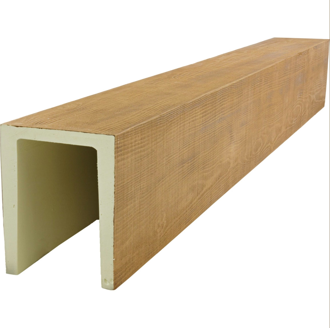
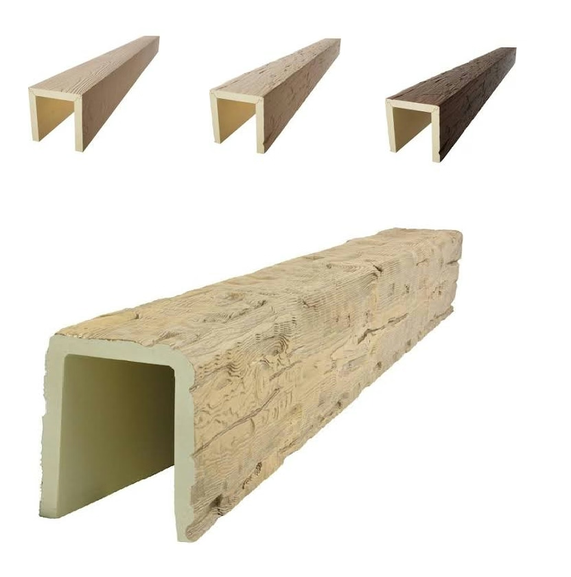
PU faux beams serve an exclusively decorative purpose. This fundamental characteristic distinguishes them from structural timbers and shapes every decision about their installation. Understanding exactly what this means for load dynamics, attachment requirements, and performance expectations prevents both under-engineering that creates safety concerns and over-engineering that wastes resources on unnecessary reinforcement.
The non-structural designation does not mean the beams carry no load or require no attention. The beams themselves, their mounting hardware, and the attachment points all experience forces that must be properly managed. What changes is the nature of those forces and how we calculate appropriate solutions. The beams do not support the ceiling; they hang from it, and that distinction drives the engineering approach.
Clarifying Non-Structural Classification
A structural element actively carries and redistributes building loads. A floor joist, for instance, supports the weight of people, furniture, and the floor itself, transferring these loads to beams, walls, and foundations. Structural beams experience complex stress patterns including bending, shear, and compression that require careful engineering to manage safely.
A non-structural element like a PU faux beam carries only its own weight and any incidental loads applied to it. The beam does not support the ceiling, contribute to building rigidity, or affect how loads travel through the structure. Its installation requirements derive entirely from the need to support its own weight safely and maintain its position against normal environmental forces.
This distinction matters for several practical reasons. Structural modifications to the building— cutting joists, removing walls, or altering load paths— do not affect faux beams because they do not participate in those load paths. Similarly, building code requirements for structural elements do not apply to decorative beams. Installers can proceed with confidence that beam installation has no structural implications for the building.
Understanding Actual Beam Loads
Beam weight represents the primary load in any faux beam installation. PU faux beams typically weigh between one and three pounds per linear foot depending on the profile and size, compared to solid timber that might weigh eight to twelve pounds per linear foot for comparable dimensions. This dramatic weight difference simplifies attachment requirements but does not eliminate them.
The weight distributes along the beam length, creating a uniform load that mounting points along the beam must collectively support. A twelve-foot beam weighing two pounds per linear foot represents a total load of twenty-four pounds that the attachment system must support continuously. With four mounting points, each carries approximately six pounds of static load, plus allowances for dynamic forces and safety margins.
Static load from the beam itself operates continuously, but dynamic loads occur intermittently. Building movement, thermal expansion and contraction, and vibration from foot traffic or building systems all create additional forces on the attachment system. While these dynamic loads are significantly smaller than the static weight, they occur thousands of times over the installation lifespan and must be accommodated without fatigue failure.
Environmental loads include wind pressure in exterior applications and seismic forces in earthquake-prone regions. While interior beams experience minimal wind loads, large ceiling installations in buildings with significant air pressure differentials may see measurable forces. Consult local codes and engineering guidelines when installing in unusual environments or commercial buildings with sophisticated HVAC systems.
Attachment System Requirements
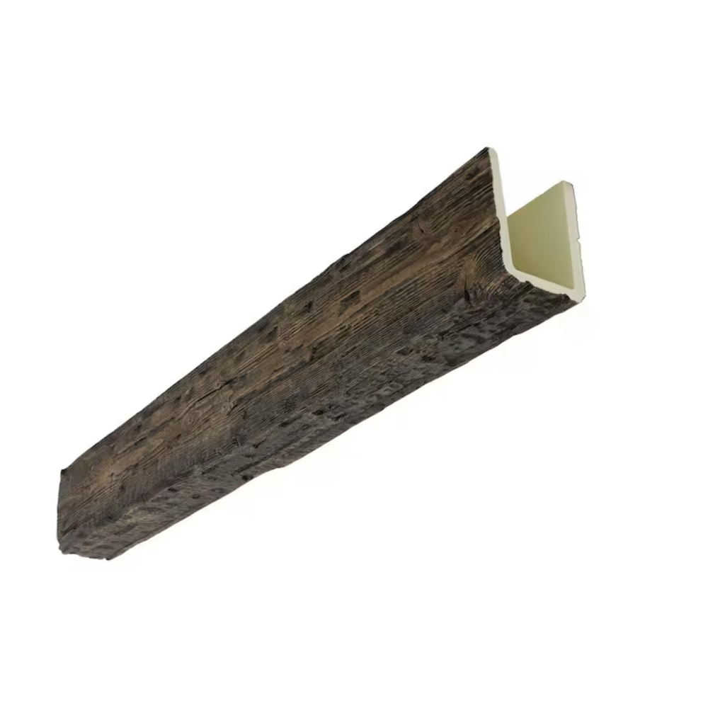
The attachment system must support beam weight with adequate safety margins while remaining hidden from view. Concealed mounting approaches use blocking, brackets, and clips that fit within the beam profile or behind the mounting surface. These systems achieve attachment without visible hardware, preserving the authentic timber appearance that makes faux beams valuable.
Fastener withdrawal resistance determines how securely brackets attach to the ceiling structure. The holding power must exceed the applied load multiplied by an appropriate safety factor. For typical installations, a safety factor of three to five provides adequate protection against unexpected loads and long-term performance degradation. Critical applications or unusual conditions may require higher safety margins.
Shear capacity matters for attachments that resist beam movement perpendicular to the mounting surface. While beams primarily stress attachments in withdrawal, any horizontal component of force also creates shear stress on fasteners. Evaluate both withdrawal and shear capacity when selecting attachment hardware, particularly for beams in high-traffic areas where accidental contact creates lateral forces.
Combined loading scenarios occur when multiple force directions act simultaneously. Real-world conditions rarely create purely axial or purely shear loads; instead, loads combine in varying proportions depending on beam position, building behavior, and environmental factors. Engineering approaches for combined loading typically use interaction formulas that account for both load types, but conservative rule-of-thumb practices simply ensure that each individual capacity exceeds requirements by generous margins.
Spacing Calculations Simplified
With the lightweight nature of PU beams, bracket spacing calculations become more straightforward than for structural applications. Maximum spacing derives primarily from aesthetic considerations— maintaining consistent appearance and preventing visible deflection under load— rather than engineering limits. Beams can typically span eight to twelve feet between supports without visible sag, though specific profiles may vary.
For standard residential installations with beams under two pounds per linear foot, bracket spacing of four to six feet provides excellent appearance and adequate safety margins. This spacing works with standard ceiling joist spacing in most homes, where joists at sixteen or twenty-four inch intervals provide convenient attachment points. Adjust spacing based on actual beam weight and profile characteristics.
Longer spans may require intermediate support to maintain appearance even when engineering allows greater distances. Visible deflection, even if structurally acceptable, creates an unprofessional appearance that clients reject. When spans exceed aesthetic comfort levels, add blocking or bracket supports to reduce the apparent span, even if technically unnecessary for load purposes.
Cantilevered installations— beams extending beyond their final support— require particular attention because the loading creates higher stresses at the support point. Limit cantilever length to approximately one-quarter of the total beam length or the span between adjacent supports, whichever is smaller. Exceeding these limits creates aesthetic problems and may stress attachments beyond comfortable margins.

Building Code and Compliance Considerations
Building codes typically distinguish between structural and non-structural elements, applying different requirements to each. Faux beams generally fall under non-structural categories that require only basic attachment without engineering analysis. However, local codes vary, and some jurisdictions may impose additional requirements for ceiling-hung elements based on seismic considerations or other factors.
If code questions arise, consult with local building officials before beginning installation. Many jurisdictions have provisions for decorative elements that simplify compliance, while others may require specific documentation or inspection. Early communication prevents costly corrections after installation is complete.
Insurance considerations occasionally affect installation decisions, particularly for commercial properties or rental housing. Building owners may require engineering documentation or specific installation methods to satisfy insurance requirements. Understanding these requirements before beginning work prevents disputes and ensures completed installations meet all stakeholder expectations.
Document the non-structural nature of the installation in project records, including calculations demonstrating that attachment meets appropriate load requirements. This documentation protects both the installer and building owner by providing evidence of professional practice. Should questions arise later, documentation of proper engineering approach demonstrates due diligence.
Technical References
ASTM standards cited in every specification
Test Data
Lab results from internal testing program
Updated 2026
Reviewed against current product specs